


There are many different types of threads for CNC machining, each with its own distinct design rules and levels of precision required. Understanding the types of threads and how to incorporate them into your designs and final parts is vital. It's not an exaggeration to say that getting threads right can make or break final assemblies.
This article covers practical information on designing and manufacturing threads using CNC machining.
Did you know we offer local sourcing for CNC machining?
What’s the difference between external and internal threading?
Let’s take a quick sidestep to cover this fundamental difference. External threading appears on screws and bolts, while internal threads can be found inside the component you’re designing and manufacturing. Internal threads lock in threads from screws and bolts (external).
It’s essential to know how to recognize the difference between external and internal threading in your technical drawing.
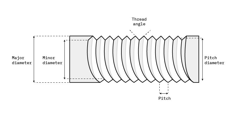
What are the main parameters for indicating threads?
-
Thread series: thread profiles (such as UN and Metric)
-
Thread type: within the thread series you have different thread types, including UNC and UNF for UN, and M and MJ for Metric
-
Nominal diameter/major diameter/thread size: these indicate thread size, referring to the major diameter of the thread
-
Pitch: the distance a point moves parallel to the axis in one revolution
-
Depth: how deep a thread is cut into a hole (can be thru or blind)
-
Allowances: allowable tolerances of a thread fit
-
Class fit/tolerance/allowance: this defines the tolerance range of thread dimensions, including major, minor and pitch diameters or internally or externally threaded parts
We suggest using standard drill sizes, as custom tooling costs a fair amount extra and adds to the production time.
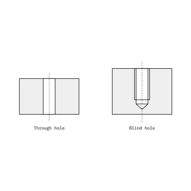
What are blind holes and through holes?
One factor you have to consider when cutting a thread is whether you need to drill a blind or a through hole. Blind holes do not go all the way through your part, so you need to specify their depth. A through hole, in contrast, goes all the way through the surface of your component. Its depth will share the thickness of the wall it cuts through.
What are the different thread types?
There are many different thread types to choose from, the most common being metric and unified. Let’s break down the different types of threads here.
-
Metric threads (M): Metric threads are the metric international standard that follows ISO. They are one of the most common threads.
-
Unified threads (UNC, UNF, UN, UNEF): Imperial standard, typically consist of coarse (UNC) and fine (UNF) threads. UN is used for a set of specific thread series that has uniform or constant threads per inch.
-
Pipe threads (National pipe) (NPT/NPS/NPTF): Typically used for threaded pipe fittings.
-
Multi-start threads: These consist of two or more intertwined threads running parallel to one another.
-
British Standard Pipe (BSPT): Typically used for threaded pipe fittings.
-
Thorlabs: Branded threads for creating adaptors for Thorlabs’ optical equipment.
-
ACME: A type of trapezoidal thread.
Want to learn how to assemble 3D-printed parts with threaded fasteners?
How do you call out metric and UN threads? What are the recommended tolerances for internal and external threads?
The following threads are the simplest type of threads and are understood by both local and global suppliers. The dimensions should be placed on the view that describes the feature most clearly.
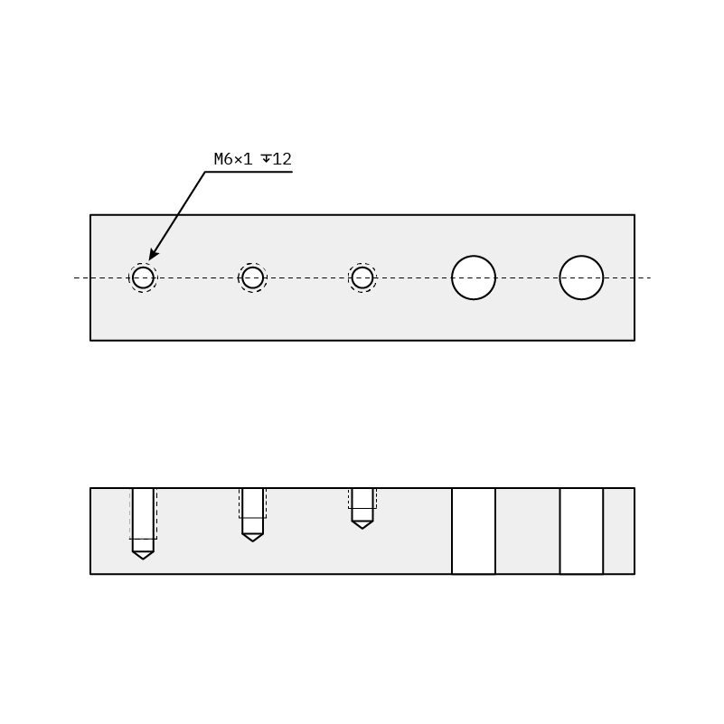
Metric threads
As a standard, you can define metric threads by simply putting the type and size (e.g. M10). The size, as mentioned above, is defined by the nominal diameter (major diameter) of the thread. The pitch and depth will follow the common metric common standards. Depths for blind holes must always be indicated.

Class fit for metric threads
Class fit defines the tolerance of the threads, and is also sometimes referred to as "allowance" or "thread fit." Internal thread tolerances are always written with capital letters and external threads are in lowercase. The standard thread tolerances are 6H for internal threads and 6g for internal threads, which is what your supplier will default to if you don’t call out any different tolerances in your drawing.
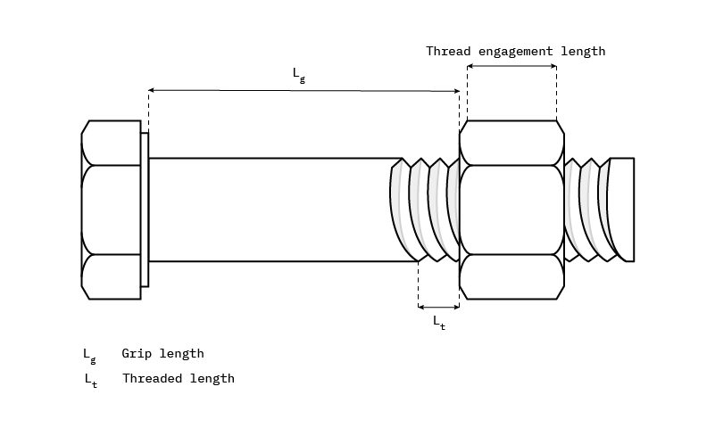
The class fits are typically defined by ISO 965-1, based on the thread engagement length. The thread engagement length denotes the length of your assembly, which will be useful for your load-bearing calculations, as friction changes with this thread engagement.
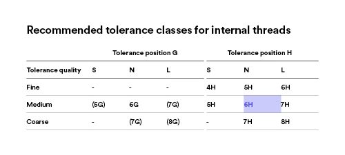
The default thread engagement length considered is N, which denotes a typical screw/screw hole connection. Therefore, the class fits default to “medium” which is 6H for (internal threads) and 6g (for external threads), as highlighted below.
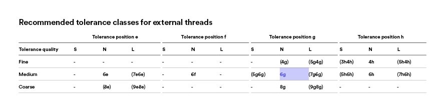
The tolerance position determines the type of tolerance to be used. The main ones are G/g and H/h.
-
G (internal) or g (external) tolerances define a tolerance changing with pitch diameter
-
H (internal) or h (external) tolerances define a static tolerance that does not change with pitch diameter
Sometimes, you will see both internal and external threads call out for one individual thread. This indicates an assembly fit, for example:
-
6H/6g
Metric threads in practice
-
Standard ISO thread: M10 x 1.5 - 6H THRU LH
-
Standard ISO thread: M10
With metric threads, you can get away with a very simple call-out, like in the second example, where you only indicate the thread series (M) and size (10). In this case, the rest will default to standard. Remember that for blind holes, you also must indicate the depth of the thread, as there is no standard to fall back to (see the table below).
| Thread series | Thread size (nominal diameter) | Pitch | Class fit | Depth | Modification |
|---|---|---|---|---|---|
| M | 10 | 1.5 | 6H | THRU | LH - left hand thread |
| M | 10 | Not indicated - default to standard pitch for this thread size (table) | Not defined - default to 6H | Not indicated so default to THRU for thru holes. For blind holes, this indication would be incomplete | Not indicated - default to RH (right hand) |
What are unified (UN) threads?

Class fit - Unified threads (UN)
Remember that class fit defines the tolerance range of thread dimensions, this is always coupled up with an indication of whether the thread is external (B) or internal (A). There are 6 types of class fit for unified threads:
-
Classes 1A and 1B - Loosest tolerance, it’s very rare. Usually used when quick assembly/disassembly is required.
-
Classes 2A and 2B - “Medium” tolerance, it’s the most common fit. This is the best option to balance thread performance and convenience.
-
Classes 3A and 3B - Very tight tolerance. Used when the threads are critical to the safety of the service of the final product.
If no fit is indicated, the default class fit is 2A for internal threads, and 2B for external threads.
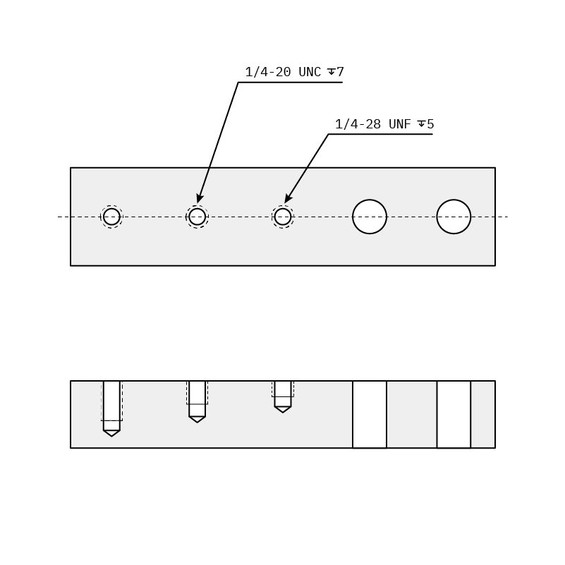
Unified threads in practice
Here are some examples for your handy reference:
-
0.250 - 20UNC - 2A MOD
-
1/4" x 20 UNC
-
#4-20 UNC
-
0.375 - 24UNEF - 2B
-
10-32 UNF-2A
-
0.190-32 UNF-2A
Let’s break down these examples by each parameter of the call-out.
| Nominal diameter (major diameter/thread size) | TPI (number of threads per inch) | Thread series & type | Class fit & external/internal designation (optional) | Modification (optional) |
|---|---|---|---|---|
| 0.250 | 20 | UNC | 2A | MOD |
| 1/4" | 20 | UNC | Not defined - default to 2A | No modification |
| #4 | 20 | UNC | Not defined - default to 2A | No modification |
| 0.375 | 24 | UNEF | 2B | No modification |
| 10 | 32 | UNF | 2A | No modification |
| 0.190 | 32 | UNF | 2A | No modification |
How do you design threads to make manufacturing more efficient?
Keep it industry standard (but be region specific!)
Relying on industry standards for threading may help you save a lot of time and money in the manufacturing process. If there’s an off-the-shelf solution, there’s really no need to overcomplicate it. We recommend using standard thread types and series as much as possible.
We know that there are threads such as NPT, BSP, etc. that are also common locally but overseas suppliers tend to have issues with these unless they're specialized. I suggest always making design choices that maximize the number of manufacturers eligible to supply them. This will help us match your designs with a wider pool of manufacturers.
-
Common series: UN (namely UNC and UNF) and Metric (namely M)
-
Common sizes: UN list, Metric list
Be wary of hole sizes
One of the most common mistakes we’ve seen when we make parts containing threads (we’ve manufactured more than 6 million parts at the time of writing) is that the thread sizes do not seem to match the hole sizes they are called out in.
This is a problem because it leads to confusion on whether it’s the right thread size and the diameter of the hole is wrong or vice-versa. As manufacturers, we cannot make assumptions, and this confusion leads to a delay in manufacturing time (1-2 days at least).
Call out thread depths on blind holes
Another reason for manufacturing delays is incomplete thread specifications.
Blind holes are holes that do not go through the full wall thickness of the part. If you call out a thread on a blind hole, you must always indicate the depth of the thread.
Want to start producing custom CNC-machined parts?
Our CNC machining services Upload a CAD file for a free, instant quote
UN thread chart
| Thread size | Drill size | Drill size, decimal size equivalent | Thread type |
|---|---|---|---|
| 0-80 | 3/64" | 0.0469" | UNF |
| 1-64 | 53 ga. | 0.0595" | UNC |
| 1-72 | 53 ga. | 0.0595" | UNF |
| 2-56 | 51 ga. | 0.067" | UNC |
| 2-64 | 50 ga. | 0.07" | UNF |
| 3-48 | 47 ga. | 0.0785" | UNC |
| 3-56 | 46 ga. | 0.081" | UNF |
| 4-40 | 43 ga. | 0.089" | UNC |
| 4-48 | 42 ga. | 0.0935" | UNF |
| 5-40 | 38 ga. | 0.1015" | UNC |
| 5-44 | 37 ga. | 0.104" | UNF |
| 6-32 | 36 ga. | 0.1065" | UNC |
| 6-40 | 33 ga. | 0.113" | UNF |
| 8-32 | 29 ga. | 0.136" | UNC |
| 8-36 | 29 ga. | 0.136" | UNF |
| 10-24 | 25 ga. | 0.1495" | UNC |
| 10-32 | 21 ga. | 0.159" | UNF |
| 12-24 | 16 ga. | 0.177" | UNC |
| 12-28 | 15 ga. | 0.18" | UNF |
| 1/4"-20 | 7 ga. | 0.201" | UNC |
| 1/4"-28 | 3 ga. | 0.213" | UNF |
| 1/4"-32 | 5.6 mm | 0.2204" | UNEF |
| 5/16"-18 | F | 0.257" | UNC |
| 5/16"-24 | I | 0.272" | UNF |
| 5/16"-32 | 9/32" | 0.2813" | UNEF |
| 3/8"-16 | 5/16" | 0.3125" | UNC |
| 3/8"-24 | Q | 0.332" | UNF |
| 3/8"-32 | 11/32" | 0.3438" | UNEF |
| 7/16"-14 | U | 0.368" | UNC |
| 7/16"-20 | 25/64" | 0.3906" | UNF |
| 7/16"-28 | 13/32" | 0.4063" | UNEF |
| 1/2"-13 | 27/64" | 0.4219" | UNC |
| 1/2"-20 | 29/64" | 0.4531" | UNF |
| 1/2"-28 | 15/32" | 0.4688" | UNEF |
| 9/16"-12 | 31/64" | 0.4844" | UNC |
| 9/16"-18 | 33/64" | 0.5156" | UNF |
| 9/16"-24 | 33/64" | 0.5156" | UNEF |
| 5/8"-11 | 17/32" | 0.5313" | UNC |
| 5/8"-18 | 37/64" | 0.5781" | UNF |
| 5/8"-24 | 37/64" | 0.5781" | UNEF |
| 11/16"-24 | 16.5 mm | 0.6496" | UNEF |
| 3/4"-10 | 21/32" | 0.6563" | UNC |
| 3/4"-16 | 11/16" | 0.6875" | UNF |
| 3/4"-20 | 45/64" | 0.7031" | UNEF |
| 7/8"-9 | 49/64" | 0.7656" | UNC |
| 7/8"-14 | 13/16" | 0.8125" | UNF |
| 7/8"-20 | 53/64" | 0.8281" | UNEF |
| 15/16"-20 | 57/64" | 0.8906" | UNEF |
| 1"-8 | 7/8" | 0.875" | UNC |
| 1"-12 | 59/64" | 0.9219" | UNF |
| 1"-20 | 61/64" | 0.9531" | UNEF |
| 1 1/8"-7 | 63/64" | 0.9844" | UNC |
| 1 1/8"-12 | 1 1/32" | 1.0313" | UNF |
| 1 1/4"-7 | 1 3/32" | 1.0938" | UNC |
| 1 1/4"-12 | 1 11/64" | 1.1719" | UNF |
| 1 1/4"-18 | 1 3/16" | 1.1875" | UNEF |
| 1 3/8"-6 | 1 7/32" | 1.2188" | UNC |
| 1 3/8"-12 | 1 19/64" | 1.2969" | UNF |
| 1 1/2"-6 | 1 11/32" | 1.3438" | UNC |
| 1 1/2"-12 | 1 27/64" | 1.4219" | UNF |
Metric thread chart
| Thread size | Pitch, mm | Drill size | Thread type Coarse/Fine |
|---|---|---|---|
| M1.6 | 0.35 | 1.25 mm | C |
| M1.8 | 0.35 | 1.45 mm | C |
| M2 | 0.4 | 1.6 mm | C |
| M2.2 | 0.45 | 1.75 mm | C |
| M2.5 | 0.45 | 2.05 mm | C |
| M3 | 0.5 | 2.5 mm | C |
| M3.5 | 0.6 | 2.9 mm | C |
| M4 | 0.7 | 3.3 mm | C |
| M4 | 0.75 | 3.2 mm | F |
| M4.5 | 0.75 | 3.7 mm | C |
| M5 | 0.5 | 4.5 mm | F |
| M5 | 0.8 | 4.2 mm | C |
| M6 | 0.5 | 5.5 mm | F |
| M6 | 0.75 | 5.2 mm | F |
| M6 | 1 | 5 mm | C |
| M6.3 | 1 | 5.3 mm | F |
| M7 | 1 | 6 mm | C |
| M8 | 0.5 | 7.5 mm | F |
| M8 | 0.75 | 7.2 mm | F |
| M8 | 1 | 6.9 mm | F |
| M8 | 1.25 | 6.7 mm | C |
| M9 | 1 | 8 mm | F |
| M9 | 1.25 | 7.7 mm | C |
| M10 | 1 | 8.9 mm | F |
| M10 | 1.25 | 8.7 mm | F |
| M10 | 1.5 | 8.5 mm | C |
| M11 | 1 | 10 mm | F |
| M11 | 1.5 | 9.5 mm | C |
| M12 | 1 | 11 mm | F |
| M12 | 1.25 | 10.8 mm | F |
| M12 | 1.5 | 10.5 mm | F |
| M12 | 1.75 | 10.2 mm | C |
| M14 | 1 | 13 mm | F |
| M14 | 1.25 | 12.8 mm | F |
| M14 | 1.5 | 12.5 mm | F |
| M14 | 2 | 12 mm | C |
| M16 | 1 | 15 mm | F |
| M16 | 1.5 | 14.5 mm | F |
| M16 | 2 | 14 mm | C |
| M18 | 1 | 17 mm | F |
| M18 | 1.5 | 16.5 mm | F |
| M18 | 2.5 | 15.5 mm | C |
| M20 | 1 | 19 mm | F |
| M20 | 1.5 | 47/64" | F |
| M20 | 2.5 | 17.5 mm | C |
| M22 | 1.5 | 20 mm | F |
| M22 | 2.5 | 25/32" | F |
| M24 | 1.5 | 57/64" | F |
| M24 | 2 | 22 mm | F |
| M24 | 3 | 21 mm | C |
| M26 | 1.5 | 24.5 mm | F |
| M27 | 1.5 | 1" | F |
| M27 | 2 | 25 mm | F |
| M27 | 3 | 24 mm | C |
| M30 | 1.5 | 1 1/8" | F |
| M30 | 2 | 28 mm | F |
| M30 | 3.5 | 1 1/32" | C |
| M33 | 2 | 31 mm | F |
| M33 | 3.5 | 1 11/64" | C |
| M35 | 1.5 | 33.5 mm | F |
| M36 | 1.5 | 34.5 mm | F |
| M36 | 2 | 34 mm | F |
| M36 | 4 | 32 mm | C |
UNS thread chart
| Thread size | Drill size | Drill size, decimal size equivalent | Thread type |
|---|---|---|---|
| 00-90 | 62 ga. | 0.038" | UNS |
| 6-48 | 2.9 mm | 0.1142" | UNS |
| 8-24 | 31 ga. | 0.12" | UNS |
| 8-40 | 28 ga. | 0.1405" | UNS |
| 10-28 | 23 ga. | 0.154" | UNS |
| 10-36 | 20 ga. | 0.161" | UNS |
| 10-40 | 20 ga. | 0.161" | UNS |
| 10-48 | 18 ga. | 0.1695" | UNS |
| 10-56 | 18 ga. | 0.1695" | UNS |
| 12-36 | 12 ga. | 0.189" | UNS |
| 3/16"-24 | 9/64" | 0.147" | UNS |
| 3/16"-100 | 16 ga. | 0.177" | UNS |
| 7/32"-32 | 13 ga. | 0.185" | UNS |
| 1/4"-24 | 4 ga. | 0.209" | UNS |
| 1/4"-27 | 3 ga. | 0.213" | UNS |
| 1/4"-36 | 2 ga. | 0.221" | UNS |
| 1/4"-40 | 2 ga. | 0.221" | UNS |
| 1/4"-48 | 1 ga. | 0.228" | UNS |
| 1/4"-56 | 1 ga. | 0.228" | UNS |
| 1/4"-80 | B | 0.238" | UNS |
| 9/32"-32 | 1/4" | 0.25" | UNS |
| 5/16"-20 | G | 0.261" | UNS |
| 5/16"-27 | 6.9 mm | 0.2716" | UNS |
| 5/16"-28 | J | 0.277" | UNS |
| 5/16"-40 | 7.2 mm | 0.2834" | UNS |
| 11/32"-32 | 5/16" | 0.3125" | UNS |
| 3/8"-18 | 8.1 mm | 0.3188" | UNS |
| 3/8"-20 | 8.2 mm | 0.3228" | UNS |
| 3/8"-27 | R | 0.339" | UNS |
| 3/8"-28 | R | 0.339" | UNS |
| 3/8"-40 | 8.9 mm | 0.3503" | UNS |
| 7/16"-16 | 9.5 mm | 0.374" | UNS |
| 7/16"-18 | 9.6 mm | 0.3779" | UNS |
| 7/16"-24 | 9.9 mm | 0.3897" | UNS |
| 7/16"-27 | 10.2 mm | 0.4015" | UNS |
| 7/16"-32 | 13/32" | 0.4063" | UNS |
| 7/16"-40 | 10.5 mm | 0.4134" | UNS |
| 15/32"-32 | 7/16" | 0.4375" | UNS |
| 1/2"-12 | 10.5 mm | 0.4134" | UNS |
| 1/2"-16 | 7/16" | 0.4375" | UNS |
| 1/2"-18 | 11.2 mm | 0.4409" | UNS |
| 1/2"-24 | 11.5 mm | 0.4528" | UNS |
| 1/2"-27 | 11.5 mm | 0.4528" | UNS |
| 1/2"-32 | 15/32" | 0.4688" | UNS |
| 1/2"-40 | 12 mm | 0.4724" | UNS |
| 9/16"-16 | 1/2" | 0.5" | UNS |
| 9/16"-20 | 33/64" | 0.5156" | UNS |
| 9/16"-27 | 33/64" | 0.5156" | UNS |
| 9/16"-32 | 17/32" | 0.5313" | UNS |
| 5/8"-12 | 35/64" | 0.5469" | UNS |
| 5/8"-16 | 9/16" | 0.5625" | UNS |
| 5/8"-20 | 37/64" | 0.5781" | UNS |
| 5/8"-27 | 37/64" | 0.5781" | UNS |
| 5/8"-28 | 37/64" | 0.5781" | UNS |
| 5/8"-32 | 19/32" | 0.5938" | UNS |
| 11/16"-16 | 5/8" | 0.625" | UNS |
| 11/16"-18 | 16 mm | 0.6299" | UNS |
| 11/16"-20 | 41/64" | 0.6406" | UNS |
| 11/16"-32 | 21/32" | 0.6563" | UNS |
| 3/4"-12 | 16.5 mm | 0.6496" | UNS |
| 3/4"-18 | 45/64" | 0.7031" | UNS |
| 3/4"-24 | 45/64" | 0.7031" | UNS |
| 3/4"-27 | 23/32" | 0.7188" | UNS |
| 3/4"-32 | 23/32" | 0.7188" | UNS |
| 13/16"-12 | 47/64" | 0.7344" | UNS |
| 13/16"-16 | 3/4" | 0.75" | UNS |
| 13/16"-18 | 19 mm | 0.748" | UNS |
| 7/8"-12 | 51/64" | 0.7969" | UNS |
| 7/8"-16 | 13/16" | 0.8125" | UNS |
| 7/8"-18 | 53/64" | 0.8281" | UNS |
| 7/8"-27 | 21 mm | 0.8268" | UNS |
| 7/8"-32 | 27/32" | 0.8438" | UNS |
| 15/16"-16 | 7/8" | 0.875" | UNS |
| 1"-14 | 23.5 mm | 0.9252" | UNS |
| 1"-16 | 15/16" | 0.9375" | UNS |
| 1"-18 | 61/64" | 0.9531" | UNS |
| 1"-24 | 61/64" | 0.9531" | UNS |
| 1"-27 | 24.5 mm | 0.9646" | UNS |
| 1"-32 | 31/32" | 0.9688" | UNS |
NPT/NPS thread chart
| Pipe size | Thread type | TPI | Drill size | Drill size, decimal size equivalent |
|---|---|---|---|---|
| 1/16 | NPT | 27 | C | 0.242" |
| 1/8 | NPT | 27 | Q | 0.332" |
| 1/4 | NPT | 18 | 7/16" | 0.4375" |
| 3/8 | NPT | 18 | 9/16" | 0.5625" |
| 1/2 | NPT | 14 | 45/64" | 0.7031" |
| 3/4 | NPT | 14 | 29/32" | 0.9063" |
| 1 | NPT | 11 1/2 | 1 9/64" | 1.1406" |
| 1 1/4 | NPT | 11 1/2 | 1 31/64" | 1.4844" |
| 1 1/2 | NPT | 11 1/2 | 1 23/32" | 1.7188" |
| 2 | NPT | 11 1/2 | 2 3/16" | 2.1875" |
| 1/8 | NPS | 27 | T | 0.358" |
| 1/4 | NPS | 18 | 15/32" | 0.4688" |
| 3/8 | NPS | 18 | 19/32" | 0.5938" |
| 1/2 | NPS | 14 | 19 mm | 0.748" |
| 3/4 | NPS | 14 | 61/64" | 0.9531" |
| 1 | NPS | 11 1/2 | 1 13/64" | 1.2031" |
BSPP/BPST thread chart
| Pipe size | Thread type | TPI | Drill size | Drill size, decimal size equivalent |
|---|---|---|---|---|
| 1/8 | BSPP | 28 | 8.8 mm | 0.3464" |
| 1/4 | BSPP | 19 | 11.8 mm | 0.4645" |
| 3/8 | BSPP | 19 | 15 mm | 0.5905" |
| 1/2 | BSPP | 14 | 19 mm | 0.748" |
| 3/4 | BSPP | 14 | 24 mm | 0.9449" |
| 1 | BSPP | 11 | 30 mm | 1.1811" |
| 1 1/4 | BSPP | 11 | 39.5 mm | 1.5551" |
| 1 1/2 | BSPP | 11 | 45 mm | 1.7716" |
| 2 | BSPP | 11 | 57 mm | 2.244" |
| 1/8 | BSPT | 28 | 8.4 mm | 0.3307" |
| 1/4 | BSPT | 19 | 11.2 mm | 0.4409" |
| 3/8 | BSPT | 19 | 14.5 mm | 0.5709" |
| 1/2 | BSPT | 14 | 18 mm | 0.7087" |
| 3/4 | BSPT | 14 | 22 mm | 0.8661" |
| 1 | BSPT | 11 | 30 mm | 1.1811" |
| 1 1/4 | BSPT | 11 | 38.5 mm | 1.5157" |
| 1 1/2 | BSPT | 11 | 44.5 mm | 1.7519" |
| 2 | BSPT | 11 | 56 mm | 2.2047" |
PG thread chart
| Pipe size | Thread type | Drill size | Drill size, decimal size equivalent |
|---|---|---|---|
| PG-7 | PG | 11.2 mm | 0.4409" |
| PG-9 | PG | 35/64" | 0.5468" |
| PG-11 | PG | 17.25 mm | 0.6791" |
| PG-13.5 | PG | 3/4" | 0.75" |
| PG-16 | PG | 21.25 mm | 0.8366" |
| PG-21 | PG | 1 1/16" | 1.0625" |
| PG-29 | PG | 1 13/32" | 1.4063" |
| PG-36 | PG | 1 51/64" | 1.7969" |
Frequently asked questions
What are the three imperial measurements for threads?
Within the Unified Thread Series, you have UNC (coarse pitch), UNF (fine pitch) and UNEF (extra fine pitch).
Where can you place threads?
You can place threads nearly anywhere on your part, so long as it fits the needs of your final assembly. If there are obstructions to threads in your design, our DFM tool will flag it and you’ll have to amend where you place threads.
What are common design restrictions for threading?
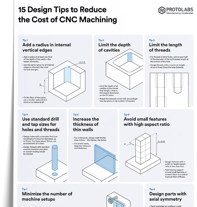
Threads longer than 0.5 times the diameter of the hole do not actually add to the strength of the connection, so design threads with a maximum length of up to three times the hole diameter.
What are the most common threads we use at Protolabs Network?
The most common type of threads are Metric threads (M), Unified threads (UN) and National Pipe threads (NPT).
How do you indicate threads on the Protolabs Network quote builder?
As of now, when you need threads in your parts, indicate them on our platform with the toggle selector, and upload a technical drawing specifying thread type, size and parameters to define your threads.


