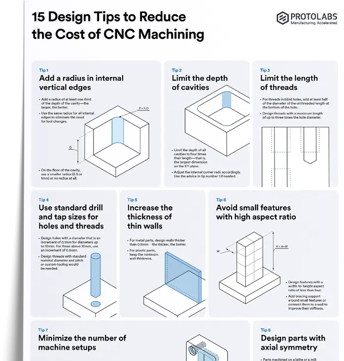
Using GD&T standards in technical drawings allows designers to communicate the most critical features and tolerances of a part to the manufacturer. This standardized method enables the manufacturer to focus on what’s most important when creating the part and understand the intent of the design.
Let’s break down the basics of GD&T and why the proper use of this method can be instrumental in getting the most out of your next 3D printing, CNC machining or injection molding production run.
Have a design that's ready to be machined?
Explore our CNC services Upload a quote for a free, instant quote
What’s the meaning of GD&T?
GD&T stands for Geometric Dimensioning and Tolerancing and it refers to the system of designating and communicating tolerances for specifications beyond the basic dimensions of the part. These functional specifications include form and size on a technical drawing.
Used properly, this system can quite effectively reduce the costs of manufacturing, mitigate potential production errors and improve the overall quality of your custom components.
What's the difference between dimensional tolerances and GD&T?
Dimensional tolerances, often called linear/size tolerances, regulate the size of all the dimensions of your custom part. Additionally, geometric tolerances determine the orientation, location, shape and size of individual features.
Geometric tolerances communicate the intent behind a design, though the focus is on feature tolerances, so they don't provide a complete picture. GD&T represents the design intent rather than the geometry that results from the design, giving you a more comprehensive picture of functionality as well.
What are the advantages of GD&T?
GD&T done right comes with many advantages, the most important of which is that it’s sometimes the exact information needed for manufacturers who may not understand the intent of the design. Manufacturers have to know how a part will be used to produce the best version of that component.
Here are some of the main advantages of the GD&T process:
-
Cost reduction: GD&T enhances the accuracy of your designs, allowing for appropriate tolerances that optimize production.
-
Optimized functionality: Explicitly stating all design requirements guarantees the accurate fulfillment of dimensional and tolerance specifications related to a part’s functionality.
-
Uniformity and convenience: GD&T is a consistent language among manufacturers. Using it reduces guesswork and misinterpreting designs, which ensures consistent geometries.
-
Accurate communication: Translating intricate designs into physical parts requires accurate and reliable communication. GD&T enables designers, manufacturers and quality teams to communicate clearly with one another, saving time and money in the process.
GD&T in action
While technical drawings for manufacturing include dimensions such as distances, diameters and angles, form and size requirements such as flatness, parallelism and concentricity are only implied by the dimensions. These requirements are not always specifically communicated.
So, when this part is machined, the quality process will ensure that the dimensions marked on the drawing are correct. Because the quality process is not required to measure flatness, for example, that property may vary across parts.
A second potential problem with this drawing is that it doesn’t specify any tolerances. No machining process can hold exactly to stated values. So, without specified tolerances, manufacturers will use standard tolerances, such as those laid out in ISO 2768. If tighter tolerances are required, such as for fit, these will not be met.
By using GD&T on technical drawings, designers can communicate exactly what’s important for the manufacturer to get right on a part. For example, in the part above, the drawing could include a parallelism specification and call out a tighter tolerance to ensure that the bore will fit properly on a mating part. This additional level of communication and definition of data on a drawing can reduce costs and lead time and improve quality.
Let’s explore the details of GD&T and how to ensure designers use it optimally in drawings for manufacturing.
What are the accepted GD&T standards?
The accepted GD&T standards are set out in ISO standards such as ISO 1101 and are used with several other ISO standards for technical drawings, such as ISO 16782. As with many other industries and areas, having the right ISO certifications may be a prerequisite for some manufacturing contracts.
In addition, the American Society of Mechanical Engineers (ASME) sets out GD&T language, use, definitions and symbols in the ASME Y14.5 standard.
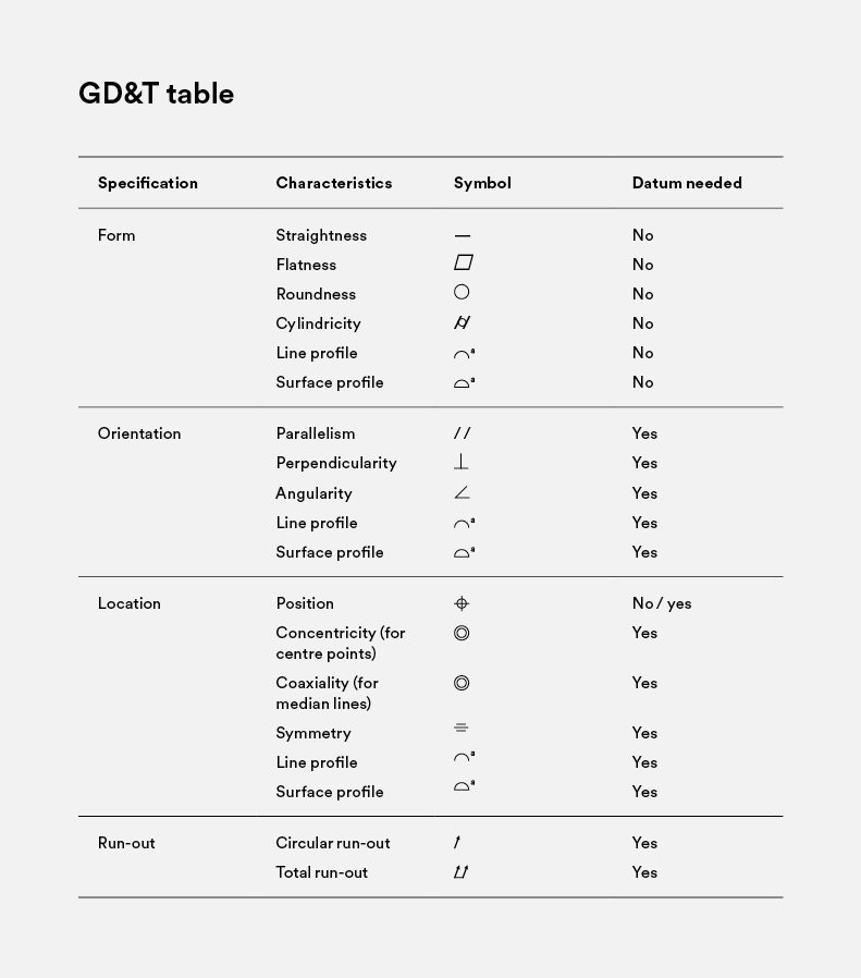
A quick guide to GD&T symbols
There are many symbols used in GD&T, which indicate the types of tolerances that machinists will check. Categories of symbols include:
-
Run-out tolerances: These control the run-out fluctuation of a feature when the part is rotated along an axis.
-
Form tolerances: These govern how features will be shaped.
-
Location tolerances: Associated with linear dimensions, these control the location of tolerances.
-
Orientation tolerances: These indicate the orientation of certain features in relation to a datum. Orientation tolerances also manage form if you apply them to the surfaces of your part.
What specifications are included in GD&T?
GD&T standards such as ISO 1101 or ASME Y14.5 are extremely detailed and set out definitions, practices and symbols for every use case and drawing need. For details on these specifications, such as flatness, circularity, and runout, please refer to official standards reference materials.
Why should you use GD&T?
The main reason to use GD&T in your drawings is to reduce your manufacturing costs. Drawings are a communication tool, and improper communication in any context can lead to additional costs and delays.
By using GD&T communication tools in your drawings to make them as clear as possible, especially the most critical features, designers ensure that manufacturers will correctly understand the purpose of the part, and ensure it is manufactured according to that purpose.
There’s a saying in engineering that goes: “anyone can build a bridge that stands, but it takes an engineer to build a bridge that barely stands.” In other words, good engineering is about achieving the desired results as efficiently as possible. GD&T is an extension of this philosophy.
These standards allow an engineer or designer to communicate to manufacturers specific features, such as the flatness of a surface or the runout of a hole. By ensuring these conditions will be met, they can loosen tolerances elsewhere on the part, reducing costs while meeting requirements.
Why should you avoid unnecessary tolerances?
It’s not always necessary to include GD&T data in your technical drawings, as many parts can be toleranced to the standard levels. Manufacturing processes follow standard tolerances, meaning that they don’t have to be specified. You only need to add them to drawings if the required tolerances are tighter than the standard.
These standard tolerances are set out in certification guidelines like ISO 2768, for instance. If designers require tighter tolerances than what is required for the function of the part, they add unnecessary costs to the manufacture of the part.
For this reason, GD&T standards are rarely used on drawings for manufacturing processes that can’t achieve precise tolerances. GD&T is generally used for subtractive processes such as CNC milling or turning, and extra machining costs definitely add up quickly.
GD&T and your order
When you submit a custom manufacturing order on our platform, our engineers and proprietary Design for Manufacturing (DFM) software review the drawing to check its manufacturability. These experts may provide feedback to customers suggesting that they loosen tolerances or change certain features of the part. For example, a larger internal corner radius is cheaper to machine than a smaller radius or worse, a sharp inside corner.
By adding GD&T specifications to your drawings, these reviewers will better understand the purpose of the part, and the review process will be better informed, providing better feedback and potentially saving time or reducing overall costs.
If you're ready to get your parts into production, you can head straight to the Protolabs Network platform to get an instant quote and explore our onboard DFM analysis. You can also reach out to networksales@protolabs.com for more information and get matched with a specialized account manager.