There are a few easy steps you can take to optimize your designs for computer numerical control (CNC) machining. By following design-for-manufacturing (DFM) rules, you can get more out of CNC machining's broad capabilities. This can be challenging though, as industry-wide specific standards do not exist.
In this article, we offer a comprehensive guide to the best design practices for CNC machining. To compile this extensive up-to-date information, we asked for feedback from industry experts and CNC machining service providers. If you are optimizing for costs, check out this guide to designing cost-effective parts for CNC.
Did you know we offer local sourcing for CNC machining?
What is the CNC machining process?
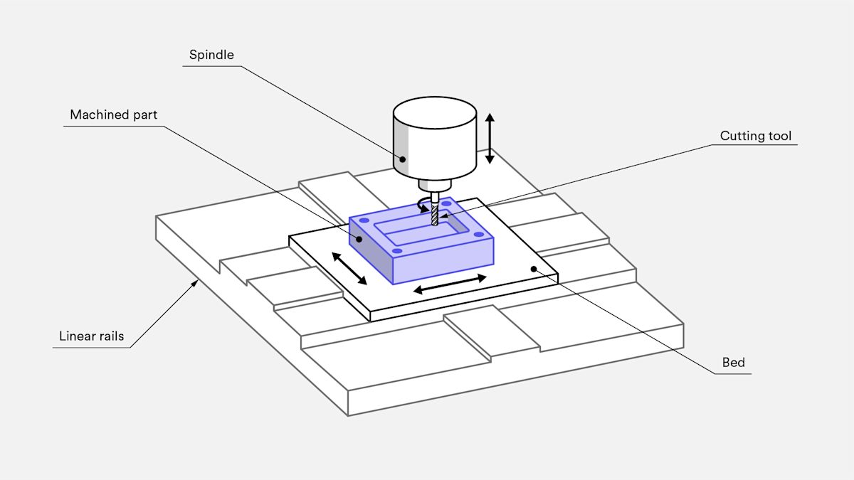
CNC machining is a subtractive manufacturing technology. In CNC, material is removed from a solid block using a variety of cutting tools that rotate at high speed—thousands of RPM—to produce a part based on a CAD model. Both metals and plastics can be CNC machined.
CNC-machined parts have high dimensional accuracy and tight tolerances. CNC is suitable for both high-volume production and one-off jobs. In fact, CNC machining is currently the most cost-effective way of producing metal prototypes, even compared to 3D printing.
Read our introduction to the basic principle of CNC machining.
What are the main restrictions of CNC design?
CNC offers great design flexibility, but there are a few restrictions. These limitations relate to the basic mechanics of the cutting process and mainly concern tool geometry and tool access.
Tool geometry
Most common CNC cutting tools (end mill tools and drills) have a cylindrical shape and a limited cutting length.
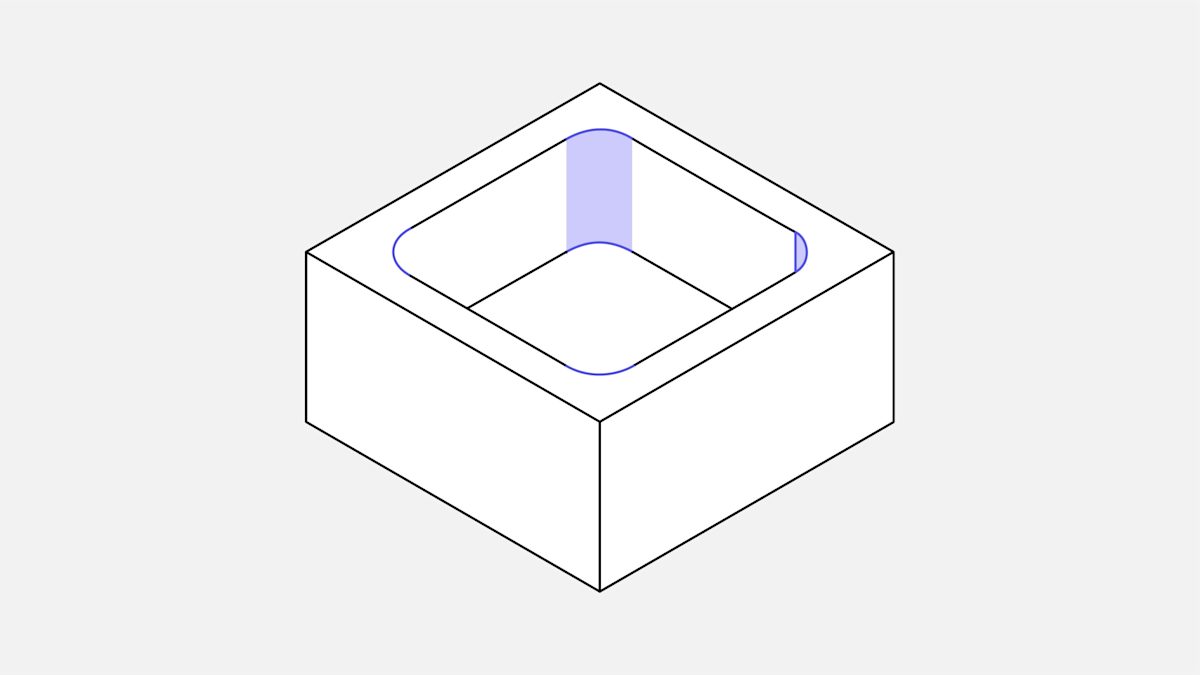
As material is removed from the workpiece, the geometry of the tool is transferred to a machined part. This means, for example, that the internal corners of a CNC part always have a radius, no matter how small a cutting tool was used.
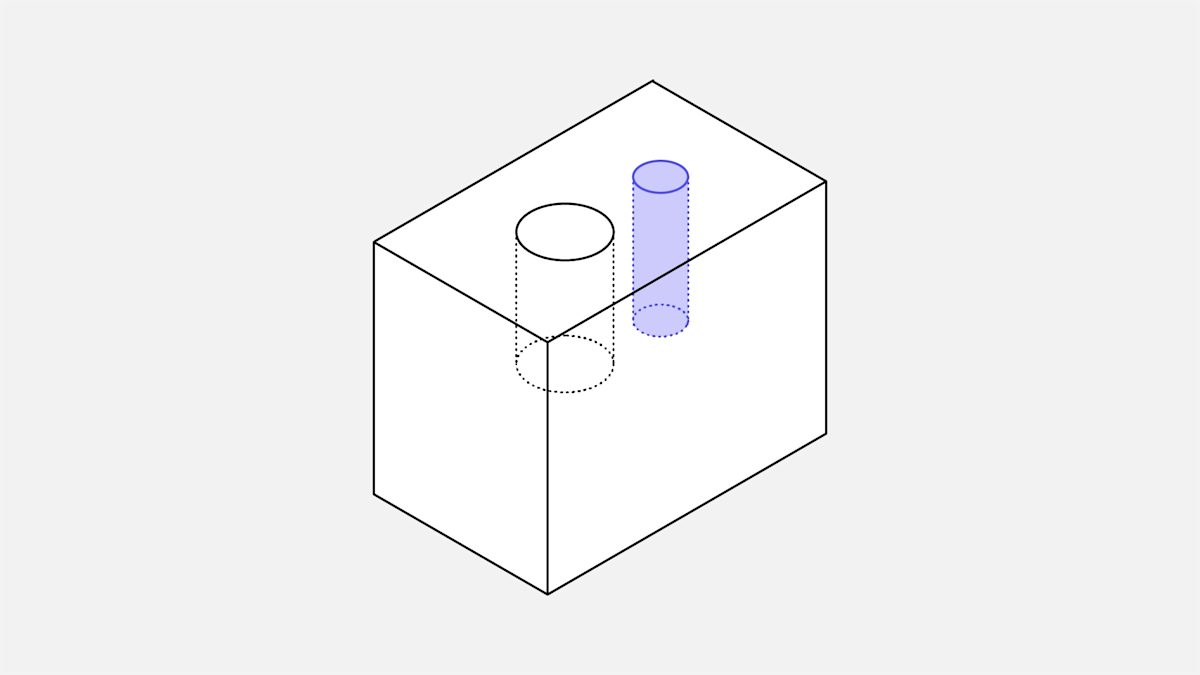
Tool access
To remove material, the cutting tool approaches the workpiece directly from above. Features that cannot be accessed in this way cannot be CNC machined.
There is an exception to this rule: undercuts. There’s a section on undercuts towards the end of this article.
We recommend aligning all your model’s features (holes, cavities, vertical walls, etc.) to one of the six principal directions. However, see this rule as a recommendation and not a restriction, as 5-axis CNC systems offer advanced workpiece-holding capabilities.
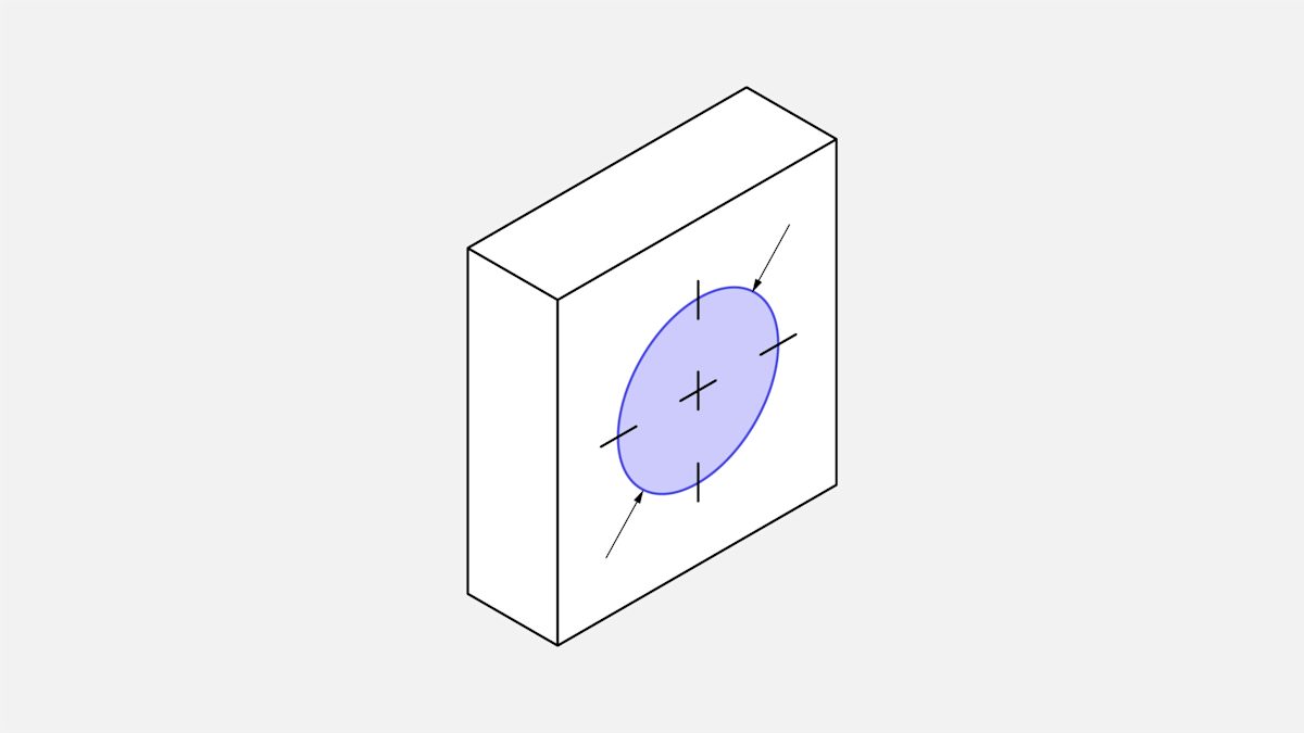
Tool access is also an issue when machining features with a large depth-to-width ratio. To reach the bottom of a deep cavity, for example, you need tools with extended reach. This means a wider range of motion for the end effector, which increases the machine chatter and lowers the achievable accuracy.
It will simplify production if you design parts that can be CNC machined with the tool that has the largest possible diameter and the shortest possible length.
CNC design guidelines
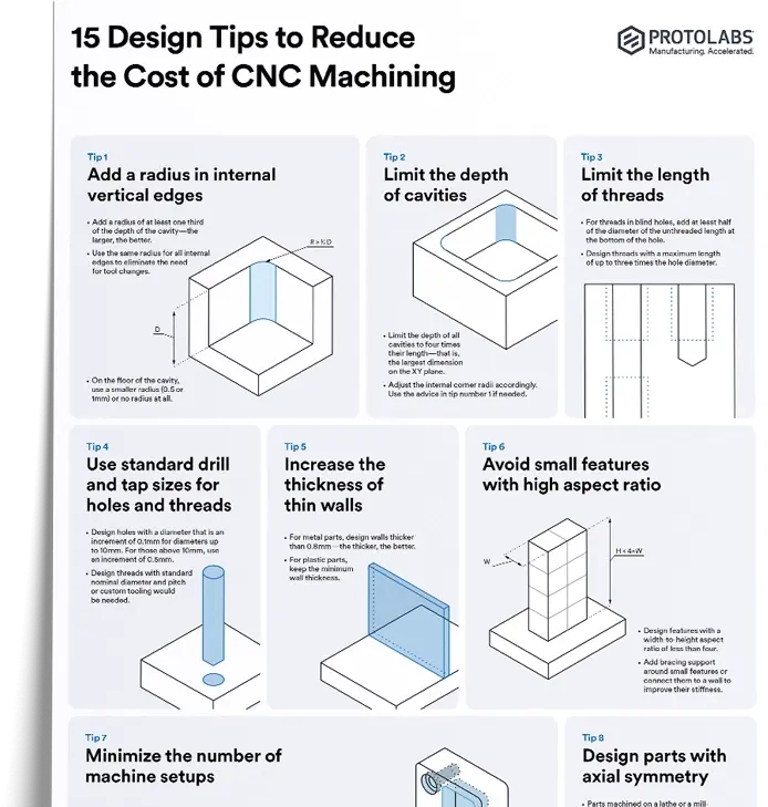
A challenge that frequently comes up while designing a part for CNC machining is that no industry-wide specific standards exist. CNC machine and tool manufacturers continuously improve the technology’s capabilities, expanding the limits of what is possible. The table below summarizes recommended and feasible values for the most common features encountered in CNC machined parts.
Cavities and pockets
Recommended cavity depth: 4 times cavity width
End mill tools have a limited cutting length (typically 3–4 times their diameter). Tool deflection, chip evacuation and vibrations become more prominent when cavities have a smaller depth-to-width ratio.
Limiting the depth of the cavity to four times its width ensures good results.
If larger depths are required, consider designing parts with a variable cavity depth.
Deep cavity milling: Cavities with depths greater than six times the tool diameter are considered deep. A tool diameter-to-cavity depth ratio of up to 30:1 is possible using specialized tooling (maximum depth: 35 cm with a 1-inch diameter end mill tool).
Internal edges
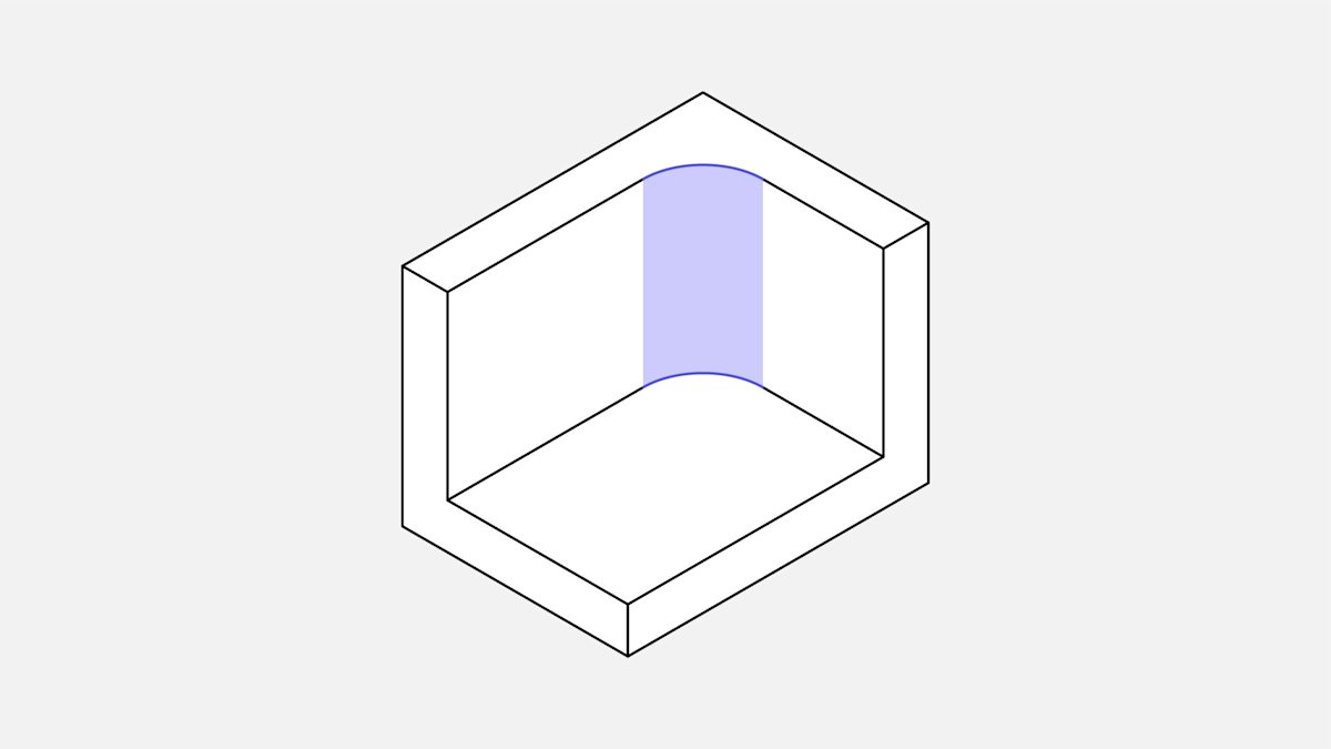
Vertical corner radius
Recommended: ⅓ times cavity depth (or larger)
Using the recommended value for internal corner radii ensures that a suitable diameter tool can be used and aligns with guidelines for the recommended cavity depth.
Increasing the corner radii slightly above the recommended value (e.g. by 1 mm), allows the tool to cut following a circular path instead of a 90 angle. This is preferred as it results in a higher quality surface finish. If sharp 90-degree internal corners are required, consider adding a T-bone undercut instead of reducing the corner radius.
Floor radius
Recommended: 0.5 mm, 1 mm or no radius
Feasible: any radius
End mill tools have a flat or slightly rounded lower cutting edge. Other floor radii can be machined using ball end tools. It is good design practice to use the recommended values, as it is preferred by the machinists.
Thin walls
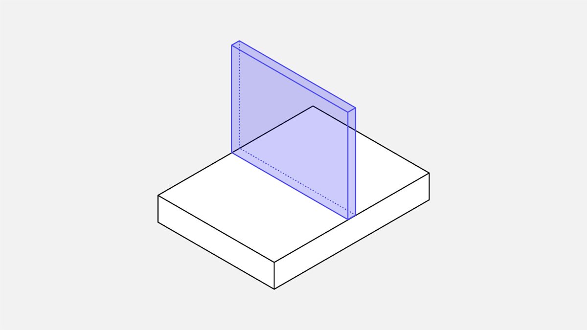
Minimum wall thickness
Recommended: 0.8 mm (metals), 1.5 mm (plastics)
Feasible: 0.5 mm (metals), 1.0 mm (plastics)
Decreasing the wall thickness reduces the stiffness of the material, which increases vibrations during machining and lowers the achievable accuracy. Plastics are prone to warping (due to residual stresses) and softening (due to temperature increase), so a larger minimum wall thickness is recommended. The feasible values stated above should be examined on a case-by-case basis.
Holes
Diameter
Recommended: standard drill bit
Feasible: any diameter larger than 1 mm
Holes are machined using either a drill bit or an end mill tool. The size of the drill bits is standardized (in metric and imperial units). Reamers and boring tools are used to finish holes that require tight tolerances. For high-accuracy holes with a diameter smaller than 20 mm, using a standard diameter is recommended.
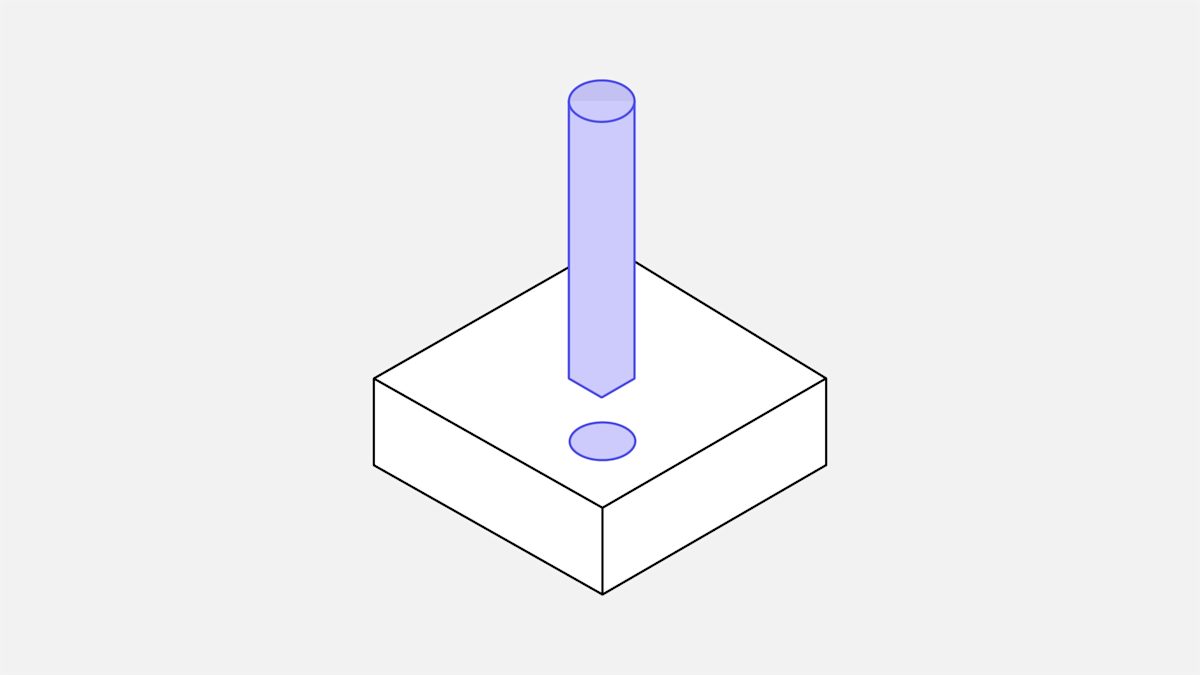
Maximum depth
Recommended: 4 times nominal diameter
Typical: 10 times nominal diameter
Feasible: 40 times nominal diameter
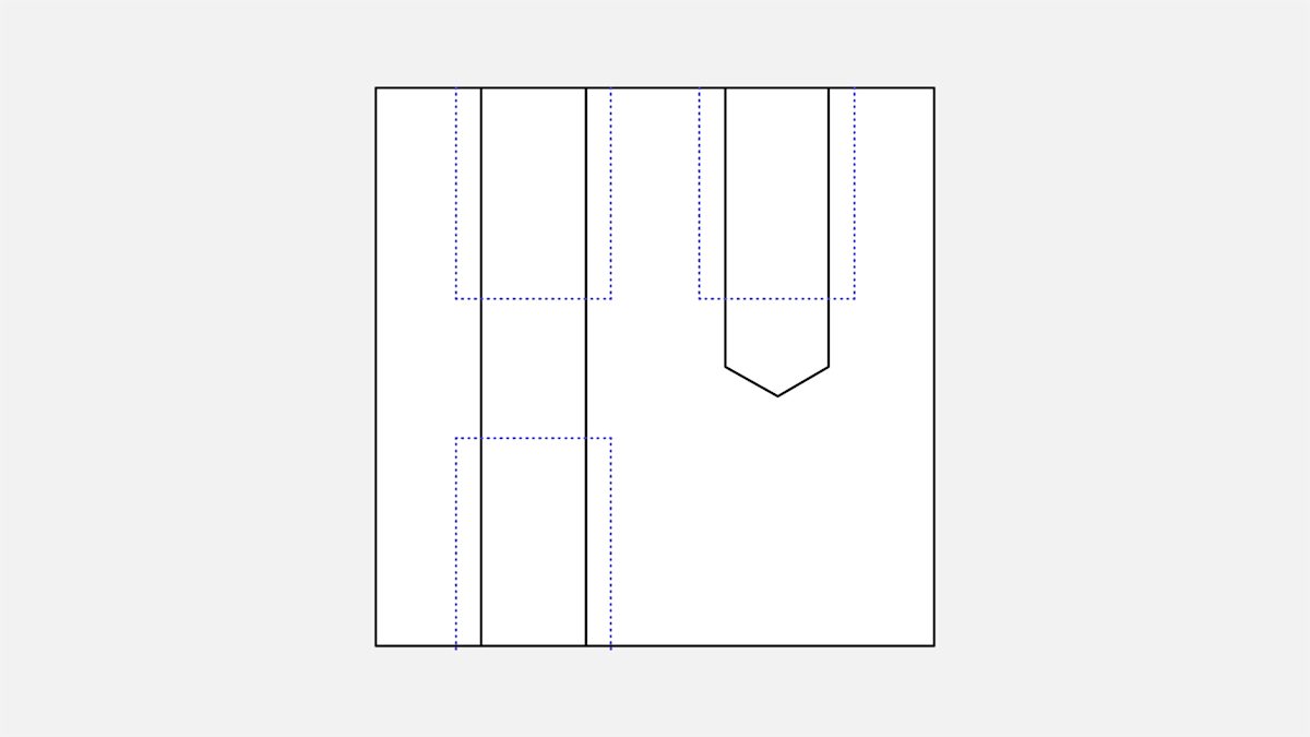
Holes with a non-standard diameter must be machined with an end mill tool. In this case, the maximum cavity depth restrictions apply and the recommended maximum depth value should be used. Holes deeper than the typical value are machined using specialized drill bits (with a minimum diameter of 3mm). Blind holes machined with a drill have a conical floor (135-degree angle), while holes machined with an end mill tool are flat.
There is no particular preference between through holes or blind holes in CNC machining.
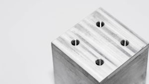
Threads
Thread size
Minimum: M1 (and lower, in some cases)
Recommended: M6 or larger
Threads are cut with taps and external threads with dies. Taps and dies can be used to cut threads down to M2. CNC threading tools are common and are preferred by machinists, as they limit the risk of tap breakage. CNC threading tools can be used to cut threads down to M6.
Thread length
Minimum: 1.5 times nominal diameter
Recommended: 3 times nominal diameter
The majority of the load applied to a thread is taken by the few first teeth (up to 1.5 times the nominal diameter). Threads longer than 3 times the nominal diameter are thus unnecessary.
For threads in blind holes cut with taps (i.e. all threads smaller than M6), add an unthreaded length equal to 1.5 times the nominal diameter at the bottom of the hole. When a CNC threading tool can be used (i.e. threads larger than M6), the hole can be threaded throughout its length.
Small features
Minimum hole diameter
Recommended: 2.5 mm (0.1 inches.'')
Feasible: 0.05 mm (0.005 inches.'')
Most machine shops can accurately machine cavities and holes using tools down to 2.5 mm (0.1 inches) in diameter. Anything below this limit is considered micro-machining. Specialty tools (micro-drills) and expert knowledge are required to machine such features because the physics of the cutting process change with this scale. Unless absolutely necessary, the recommendation is therefore to avoid them.
Tolerances
Typical: +-0.1 mm
Feasible: +-0.02 mm
Our tolerances are either 2768 medium or fine. If tolerances are not specified, manufacturing partners will use the selected 2768 grade.
Tolerances define the boundaries for an acceptable dimension. The achievable tolerances vary according to the base dimension and the geometry of the part. The values above are reasonable guidelines.
Text and lettering
Recommended: font size 20 (or larger), 5 mm engraved
Engraved text is preferred over embossed text, as less material is removed. Using a minimum size of -20 sans -serif font (e.g. Arial or Verdana) is recommended. Many CNC machines have pre-programmed routines for these fonts.
CNC machine setups and parts orientation
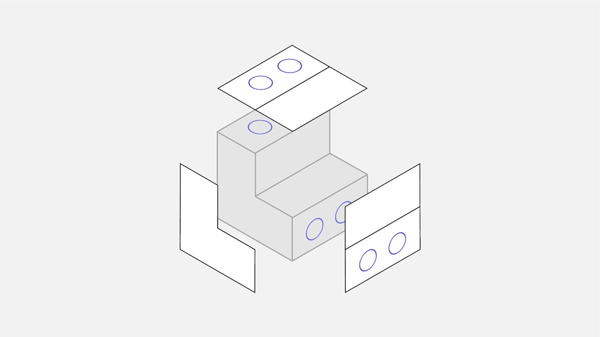
Tool access is one of the main design limitations in CNC machining. To reach all surfaces of the model, the workpiece has to be rotated multiple times.
Whenever the workpiece is rotated, the machine has to be recalibrated and a new coordinate system has to be defined.
While designing, it is important to consider machine setups for two reasons:
-
The total number of machine setups affects the cost. Rotating and realigning the part requires manual work and increases total machining time. This is often acceptable if the part needs to be rotated up to three or four times, but anything above this limit is excessive.
-
To achieve maximum relative positional accuracy, two features must be machined in the same setup. This is because the new calibration step introduces a small (but non-negligible) error.
What is 5-axis CNC machining?
A 5-axis CNC machine moves cutting tools or parts along five axes at the same time. Multi-axis CNC machines can manufacture parts with complex geometries, as they offer two additional rotational axes. These machines eliminate the need for multiple machine setups.
What are the advantages and limitations of 5-axis CNC machining?
Five-axis CNC machining allows the tool to remain constantly tangential to the cutting surface. The tool paths can be more intricate and efficient, resulting in parts with better surface finish and lower machining times.
That said, 5-axis CNC has its limitations. Basic tool geometry and tool access limitations still apply (for example, parts with internal geometries cannot be machined). Moreover, the cost of using such systems is higher.
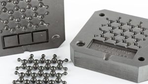
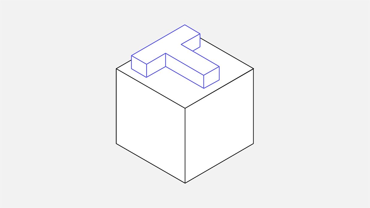
CNC machining undercuts
Undercuts are features that cannot be machined using standard cutting tools, as some of their surfaces are not accessible directly from above.
There are two main types of undercuts: T-slots and dovetails. Undercuts can be one-sided or double-sided and are machined using special tools.
T-slot cutting tools are made of a horizontal cutting blade attached to a vertical shaft. The width of an undercut can vary between 3mm and 40mm. We recommend using standard sizes for the width (i.e. whole millimeter increments or standard inch fractions), as it is more likely that an appropriate tool is already available.
For dovetail cutting tools, the angle is the defining feature size. Both 45- and 60-degree dovetail tools are considered standard. Tools with an angle of 5-, 10- and up to 120-degree (at 10 degree increments) also exist but are less commonly used.
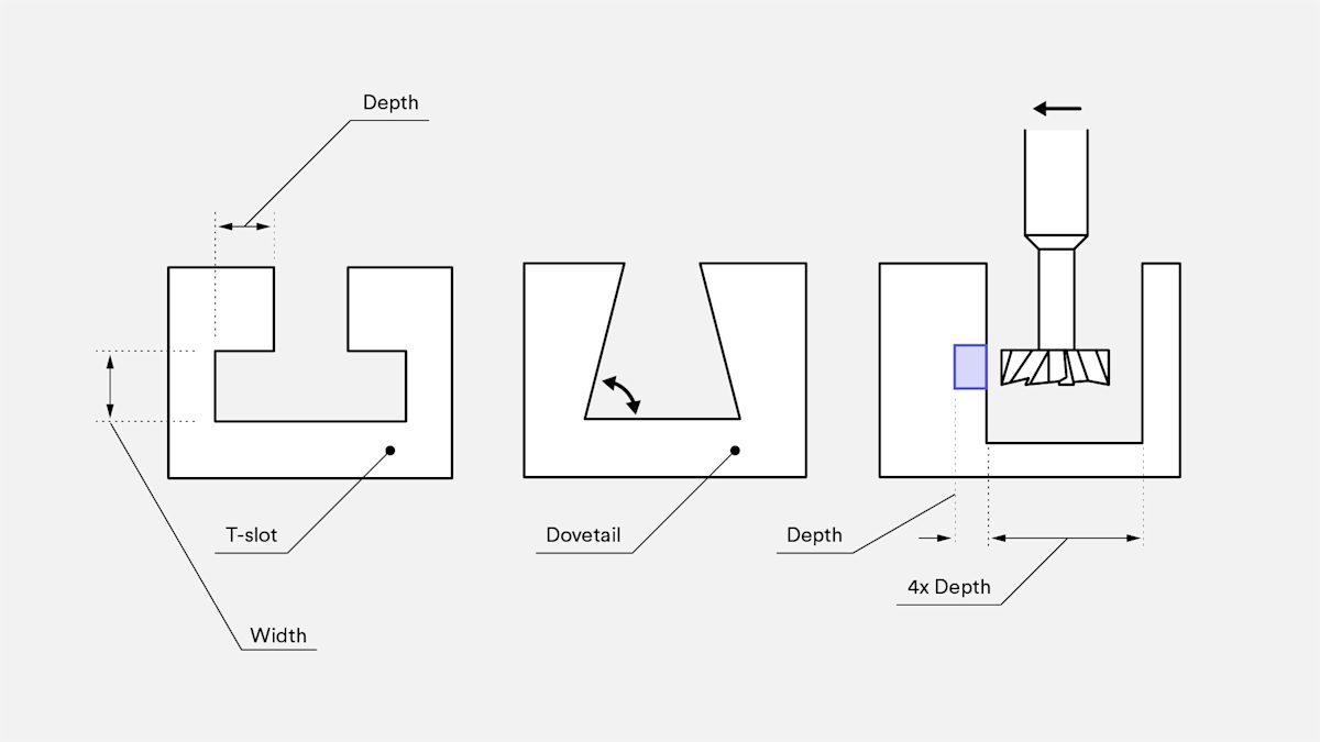
Undercut design for CNC machining
When designing parts with undercuts on internal walls, remember to add enough clearance for the tool. A good rule of thumb is to add space equal to at least four times the depth of the undercut between the machined wall and any other internal wall.
For standard tools, the typical ratio between the cutting diameter and the diameter of the shaft is 2:1, thereby limiting the cutting depth. When a non-standard undercut is required, it is common practice for machine shops to manufacture their own custom undercut tools. This can add to lead time and cost, so avoid it if possible.
Drafting a technical drawing
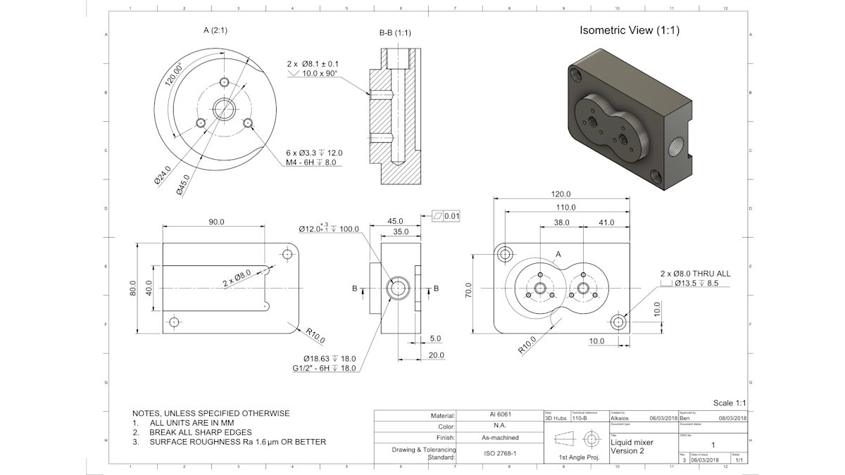
Technical drawings are sometimes used by engineers to communicate specific manufacturing requirements to the machinist. If you are interested in the topic, read this article about how, when and why to use technical drawings.
Uploading a technical drawing with your quote
We don’t usually require a technical drawing for orders on our platform, but in some cases, they can add valuable context to a quote request. Certain design specifications cannot be included in a STEP or IGES file. For example, you’ll have to include a 2D technical drawing if your model includes threaded holes or shafts and/or dimensions with tolerances tighter than the selected 2768 grade.
If you add a technical drawing, please make sure it matches the specifications of the files uploaded. If the technical drawings do not match the files uploaded or the quote specifications:
-
The quote specifications are considered the point of reference for the technology, material and surface finishes.
-
The technical drawings are considered the point of reference for the thread specifications, tolerance specifications, surface finish details, part marking requests and heat treatment specifications.
-
The CAD file is considered the point of reference for the part design, geometry, dimension and feature locations.
For further details, read our specifications policy.
What are the best practices for CNC machining?
-
Design parts that can be machined using the tool with the largest possible diameter.
-
Add the large fillets (at least ⅓ times the cavity depth) to all internal vertical corners.
-
Limit the depth of cavities to 4 times their width.
-
Align the main features of your design with one of the six principal directions. If that is not possible, 5-axis CNC machining is an option.
-
Submit a technical drawing with your drawing if your design includes threads, tolerances, surface finish specifications or other notes for the machine operator.
Have parts you need CNC machined? Upload your designs and our DFM tool will suggest optimizations and provide instant pricing.