Thin walls are often the first feature to fail. Use these guidelines to hit minimum thickness targets for your 3D printing process.
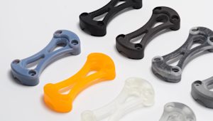
Thin walls are everywhere in product design. They reduce weight, save material, and let you pack more functionality into less space. But when it comes to 3D printing, thin features test the limits of what each process can reliably produce.
A wall that's too thin might not print at all. Or worse, it'll print but crack under normal handling. Minimum wall thickness varies by technology, and meeting it means considering material choice, orientation, and support strategy.
This guide covers the design considerations for thin-walled parts across FDM, SLA, SLS, MJF, and other common processes.
Why thin walls are challenging in 3D printing
3D printing builds parts layer by layer, which introduces some specific challenges when you're designing thin walls. These features have less material to distribute stress and are especially vulnerable at the layer interfaces. As each layer heats and cools, thin sections are more likely to warp, crack, or delaminate.
The risks vary depending on which 3D printing process you choose.
-
FDM deposits molten plastic through a nozzle, so wall thickness depends on nozzle diameter and how well passes fuse together.
-
SLA cures liquid resin with a laser, creating smooth surfaces but potentially brittle thin sections.
-
Powder-bed processes like SLS and MJF don’t need supports, but thin walls can still warp or soften from heat buildup, especially if the orientation isn’t ideal.
-
DMLS (offered through Protolabs Europe) builds metal parts with intense localized heat. Thin walls in metal prints can warp due to thermal stress if not carefully supported and controlled.
No matter the process, our DFM (Design for Manufacturability) tool catches all thin-wall risks right when you upload your CAD, so you can make changes before production starts.

Minimum wall thickness by 3D printing process
Each printing technology has its own practical limits for how thin you can go.
| Process | Min wall (supported / free) | Min feature size | Layer thickness | Dimensional accuracy | Surface finish | Warping risk | Notes |
|---|---|---|---|---|---|---|---|
| FDM | 0.8 / 0.8 mm | 2.0 mm | 100–300 μm | ±0.1–0.2 mm | Layer lines visible | High | Budget-friendly, fast |
| SLA | 0.5 / 1.0 mm | 0.2 mm | 50–100 μm | May shrink post-cure | Smooth | Low–moderate | Best for details |
| SLS | 0.8 / 1.0 mm | 0.5 mm | 100 μm | ±0.3 mm | Matte, grainy | Low | Self-supporting |
| MJF | 0.7 / 1.0 mm | 0.5 mm | 80 μm | ±0.3 mm | Clean, detailed | Low | High repeatability |
| DMLS | 0.4–0.8 / 0.8–1.5 mm | — | — | Geometry-dependent | Rough | High | Metal; thermal stress |
These are general guidelines. Your actual limits depend on part geometry, material choice, and post-processing. A 0.5 mm wall might work fine in a small, protected area but fail in a large, unsupported span.
Material considerations for thin walls
Not all materials handle thin walls equally well. Some materials can tolerate thin sections without issue, while others become prone to failure when pushed too far.
-
Stress response: Materials that flex under stress (like nylon and TPU) handle thin walls better than rigid materials (ABS, PLA, standard resins) that crack under stress. If your part needs to bend or absorb impact, choose a flexible or tough material.
-
Printability at thin dimensions: Nylon and resins generally print cleanly at minimum wall thickness. TPU can be challenging due to stringing and poor layer adhesion at very thin sections. ABS and PLA print reliably but become brittle, so careful orientation is critical.
-
Stiffness vs. brittleness tradeoff: Filled materials (carbon/glass fiber) and polycarbonate offer high stiffness but crack more easily in thin sections. If you need stiffness, reinforce thin walls with ribs rather than relying on material properties alone.
| Material / Family | Thin wall performance | Best use case | Watch out for |
|---|---|---|---|
| Nylon (PA12/PA11) | Excellent, tough and slightly flexible | Functional parts under stress or impact | May flex more than stiffer materials |
| TPU | Good, absorbs stress without cracking | Parts needing flexibility or shock absorption | Harder to print cleanly at very thin sections |
| PLA, ABS | Fair, prints reliably but brittle | Budget prototypes or low-stress parts | Cracks easily; avoid sharp corners and impacts |
| Standard SLA resin | Good, fine detail, smooth finish | Cosmetic parts or detailed prototypes | Brittle unless using tough resin variants |
| Filled materials | Poor, notch-sensitive | Structural parts where you can add ribs | Very prone to cracking at thin sections |
| Polycarbonate | Fair, strong but warp-prone | High-temp or high-strength applications | Requires thermal control; cracks if stressed |
Build orientation guidelines
How you design the orientation of your part has a big effect on thin wall strength and print reliability.
-
Orient for layer strength: Align thin walls so the main loads run within the layer plane (XY) and avoid loading them in Z, where interlayer strength is lowest.
-
Warping: In FDM, reduce warping by breaking up large flat areas and avoiding sharp corners. In SLA, tilting can reduce peel forces, but it may increase supports, so weigh peel reduction against support marks.
-
Supports: Avoid overhangs where possible. In FDM and SLA, use 45° angles or minimal contact supports. In SLS and MJF, the powder provides natural support.
Optimizing for part strength
Thin walls don’t have to mean fragile parts. With the right reinforcement strategies, you can keep designs lightweight while improving strength and durability.
-
Add ribs: Reinforce long, thin walls with perpendicular ribs. Keep rib thickness to 50–75% of the wall and space them to support the span.
-
Use fillets: Round internal corners (≥0.5 mm radius) to reduce cracking caused by stress concentrations.
-
Try lattices: Use lattice or honeycomb structures to reinforce large thin-walled areas. They spread load efficiently and are a great fit for SLS and MJF. In SLA, they can work too, but watch for supports and trapped resin.
For more reinforcement techniques, check out our design for 3D printing guidelines
Holes, slots, and feature spacing near thin walls
Cutting into thin walls weakens them. Every hole removes material that would otherwise carry stress. Here's how to keep your parts structurally sound:
-
Spacing rule: Keep 1.5–2× the wall thickness between holes, or between a hole and the edge. Any tighter and you risk tearing.
-
Avoid small holes (<1–2 mm) if possible: They're problematic across all processes. In FDM, they may close up or need hard-to-remove supports. In SLA, they often fail to print. In SLS orMJF, powder gets trapped. Use larger holes or slots instead.
-
Use slots over circles: Slots print more reliably, especially when the long axis runs parallel to the build layers.
-
Round your corners: Sharp corners in cutouts concentrate stress and cause cracks. Use fillets if your part will flex or face repeated loads.
For more guidance on FDM design, check out our how to design parts for FDM 3D printing guide.

Supports, vents, and drain paths
Thin walls are vulnerable during part removal. Here's how to design for clean results.
-
Minimize supports: In FDM and SLA, thin overhangs often need support, but they’re difficult to remove cleanly. Use self-supporting angles (≤45°), and choose tree or minimal-contact supports where needed.
-
Add drain and vent holes: In SLA and other resin processes, hollow parts need drain holes at the lowest point and vent holes at the highest to release uncured resin and air.
-
Plan powder escape in powder-bed processes: In SLS and MJF, you don’t need supports, but hollow parts still need escape holes (and a clear path) so trapped powder can be removed.
Tolerances and surface finish on thin sections
Thin walls are more sensitive to dimensional variation. In some cases, surface finishes can help strengthen thin walls by smoothing transitions and distributing stress. In others, aggressive post-processing can thin or weaken them further.
-
Test before scaling: Thin walls under 1 mm can vary dimensionally. Order or print a sample, measure it, then adjust your design if needed.
-
Surface treatments can help—or hurt: Smoothing, polishing, or chemical finishes can reduce stress concentrations, but aggressive sanding or vapor smoothing can thin fragile walls even further. Explore our surface finishing services to choose the right post-processing method for your parts.
-
Match finish to geometry: Smooth finishes (like in SLA) are ideal for thin, cosmetic parts. Powder-based processes may need tumbling or coating to improve strength or aesthetics.
For more process-specific tips, visit the 3D printing knowledge base.
Quick checklist for designing thin walls
Before you send a thin-walled part to print, check the following:
-
Confirm minimum wall thickness for your process and material
-
Avoid long unsupported spans and sharp corners
-
Add ribs or fillets to stiffen walls
-
Orient to reduce layer stress and warping
-
Plan supports and removal strategy early
-
Test critical features with a small prototype first
Our DFM analysis tool flags thin wall issues when you upload, alerting you to features that may fail. Review the feedback and adjust your design before ordering.
Where to learn more
For additional guidance on designing parts for 3D printing, check out the following resources.
Get started
Ready to move forward with a design that’s both lightweight and high performing? Upload your design for a free, instant quote.
Frequently asked questions
What’s the thinnest wall I can print?
Can I post-process thin walls without damaging them?
Yes, but be careful. Finishing steps like polishing or vapor smoothing can remove material and weaken already-thin sections. Consider gentler finishes for delicate parts. Check our surface finishing services for specifics.