As the most affordable 3D printing technology on the market, fused deposition modeling (FDM) is a great choice for quick, low-cost prototyping and can be used for a wide variety of applications. It can also be an effective solution for functional parts, such as enclosures.
Like all manufacturing methods, FDM has some limitations and constraints on what can be printed. This article explains how you can adjust your designs for optimal FDM print quality.
What is the FDM printing process?
Fused deposition modeling (FDM) is an additive manufacturing process that uses the technique of material extrusion. Also known as fused filament fabrication (FFF), FDM is the most widely used 3D printing technology.
How do you design for FDM printing?
To achieve the best results, keep FDM’s capabilities and constraints in mind when designing a part for FDM printing.
Bridging
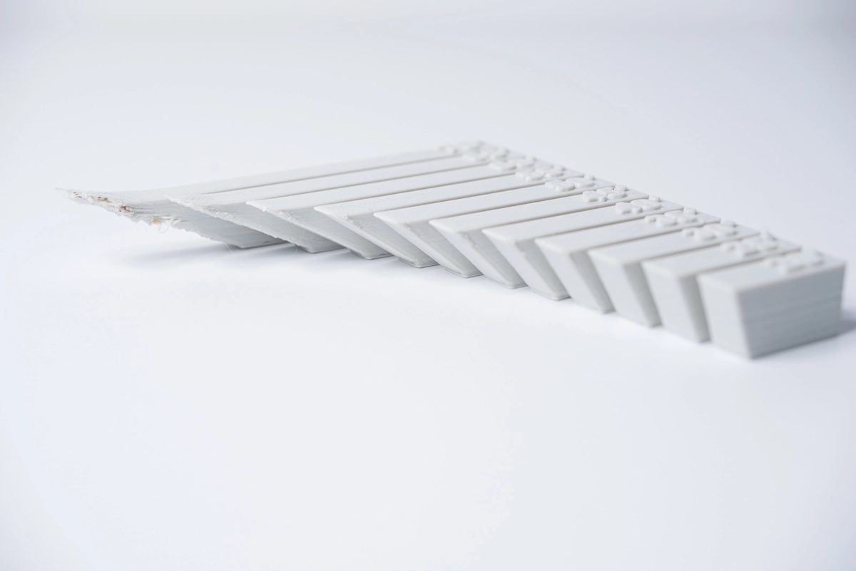
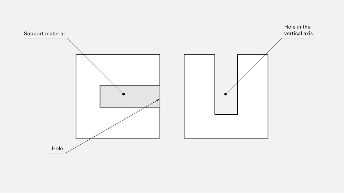
Bridging in FDM occurs when the printer is required to print between two supports or anchor points. Because there is nothing to build on, no support is offered for the initial layer being printed and the material tends to sag. Bridges most often occur in horizontal-axis holes found in the walls of objects or in the top layer (or roof) of hollow parts.
One solution is to reduce the distance of the bridge, but the impact of this depends on the part’s design constraints. Another solution to avoid sagging is to include support. Support offers a temporary platform for the bridging layer to be built upon. The support material is removed once the print is completed, although it can leave marks on or damage the surface where the support was connected to the final part.
Key design consideration: Due to the nature of FDM, sagging or marks from support material are to some extent always present unless the bridge is less than 5mm. If a smooth, level surface is required, an advanced solution is to split the design into separate parts or do some form of post-processing.
Vertical axis holes
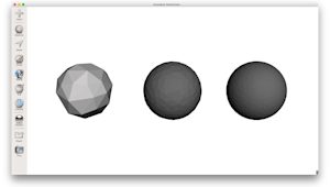
FDM often prints undersized vertical-axis holes. The printing process for such a hole and the reason its diameter gets reduced can be summarized as follows:
-
As the nozzle prints the perimeter of a vertical axis hole, it compresses the newly printed layer down onto the existing build layers to help improve adhesion.
-
The nozzle’s compressing force deforms the extruded round layer shape from a circle into a wider, flatter shape (see image below).
-
This increases the area of contact with the previously printed layer, improving adhesion but widening the extruded segment.
-
This causes a decrease in the hole diameter being printed. This decrease can be an issue, particularly when printing small-diameter holes, whereby the effect is greater due to the ratio of hole diameter to nozzle diameter.
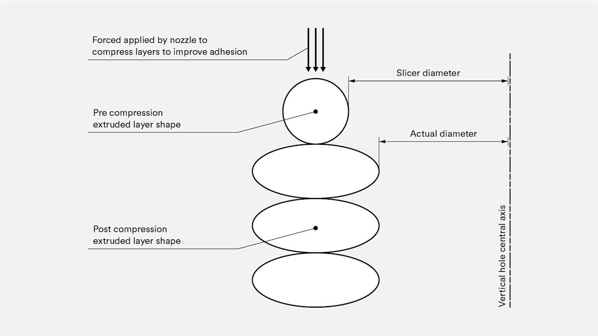
The amount of undersize depends on the printer, slicing software, hole size and material. The reduction in diameter of vertical axis holes is often taken into account by the slicing program, but accuracy can vary. Several test prints may be needed to achieve the desired accuracy. If a high level of accuracy is required, it may be necessary to drill the hole after printing.
Key design consideration: If the diameter of the vertical axis hole is critical, the recommendation is to print it undersized and then drill the hole to the correct diameter.
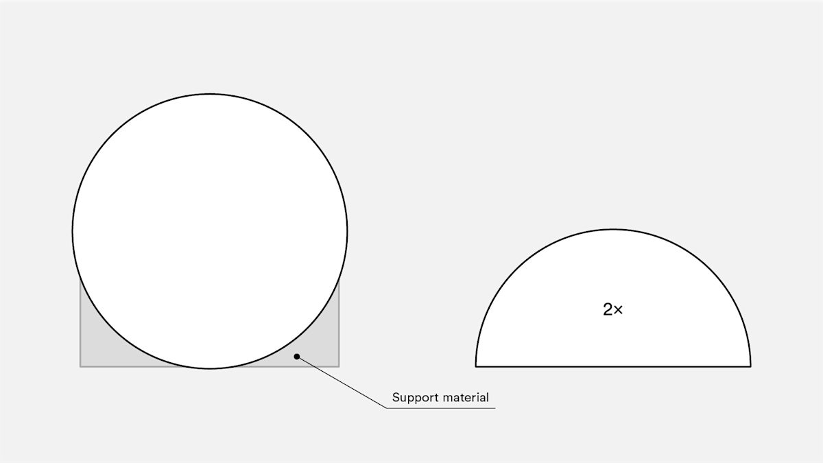
Overhangs
Issues with overhang are one of the most common FDM print-quality problems. Overhangs occur when the printed layer of material is only partially supported by the layer below. As with bridging, the inadequate support provided by the surface below the build layer can result in poor layer adhesion, bulging or curling.
Depending on the material, an overhang can usually be printed up to 45° without compromising quality. At 45°, the newly printed layer is supported by 50% of the previous layer. This creates sufficient support and adhesion to build upon. Above 45°, support is required to ensure that the newly printed layer does not bulge down and away from the nozzle.
Another issue that occurs when printing overhangs is curling. The newly printed layer becomes increasingly thin at the edge of the overhang. This results in differential cooling, causing it to deform upwards.
Key design consideration: You can overcome the limitations of overhangs by using support for wall angles above 45°. For larger overhangs needing support, expect marks to be present on the final surface unless post-processed.
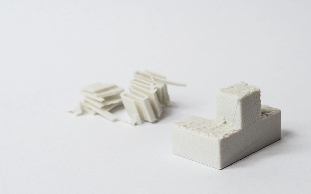
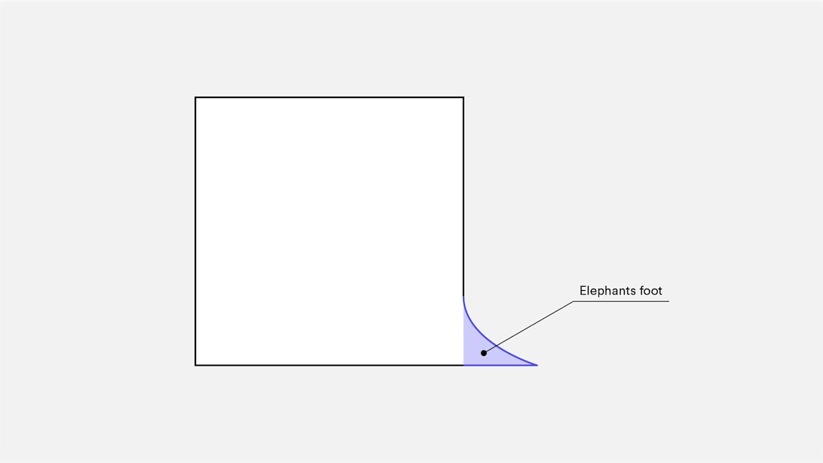
Corners
Because FDM printing nozzles are circular, corners and edges have a radius equal to the nozzle size. This means that these features are never perfectly square.
For sharp edges and corners, the first layers of a print are especially important. As discussed above for vertical holes, with each print layer, the nozzle compresses the print material down to improve adhesion. For the initial print layer, this creates a flare often called an “elephant's foot”. Protruding outside the specified dimensions, this flare can impact the ability to assemble FDM parts.
Another common issue concerning the first layer of an FDM print is warping. Compared to PLA, ABS is more vulnerable to warping due to its high printing temperature. The base is the first layer to be printed. It cools as the other hot layers are printed on top. This causes differential cooling, and can result in the base layer curling up and away from the build plate as it shrinks and contracts.
The addition of a chamfer or radius along the edges of the part that is in contact with the build plate reduces the impact of these problems. This also helps with removing the component from the build plate once the print has been completed.
Key design consideration: If assembly or overall dimensions are critical to the function of an FDM part, include a 45° chamfer or radius on all edges touching the build plate. For high-precision form-and-fit testing, we recommend other technologies such as SLA or PolyJet.
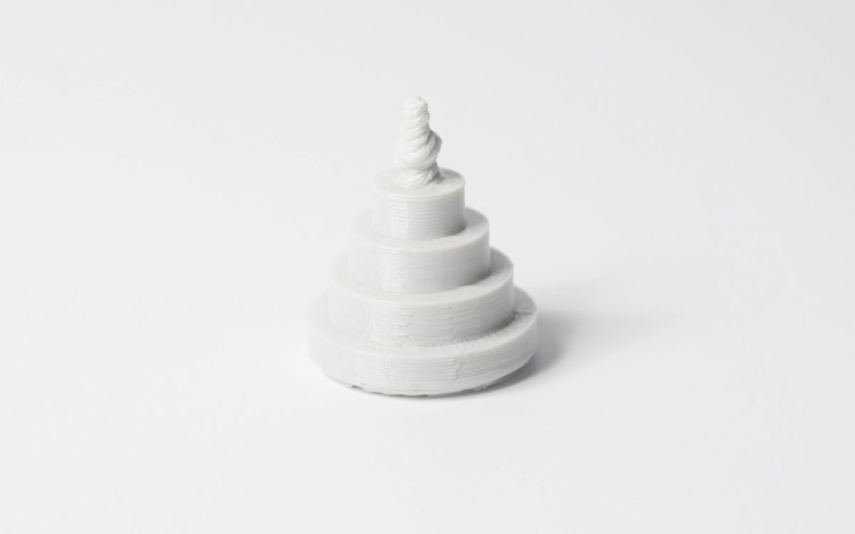
Vertical pins
Vertical pins are often printed with FDM when assembly of parts or alignment is required. It is critical to understand the size of vertical pins that FDM can accurately print since these features are often functional.
Large pins (greater than 5mm diameter) are printed with a perimeter and infill, affording a strong connection to the rest of the print. Smaller diameter pins (less than 5mm diameter) can be made up of only perimeter prints with no infill. This creates a discontinuity between the rest of the print and the pin, resulting in a weak connection susceptible to breaking. In a worst-case scenario, small pins may not print at all because there is not enough print material for the newly printed layers to adhere to.
Correct printer calibration (encompassing optimal layer height, print speed, nozzle temperature, etc.) can often reduce the likelihood of small-pin failure. The addition of a radius at the base of the pin eliminates that point as a stress concentration and adds strength. For critical pins smaller than 5mm in diameter, an off-the-shelf pin inserted into a printed hole may be the optimal solution.
Key design consideration: If your design contains pins smaller than 5mm in diameter, add a small fillet at the base of the pin. If function is critical, consider including a hole in your design in the location of the pin, drill the hole to the correct size and insert an off-the-shelf pin.
Tips for advanced FDM design
When printing with FDM, consider how to reduce the amount of support required, a part’s orientation and the direction the part is built on the build platform.
Splitting your model
Splitting a model can often reduce its complexity, saving costs and time. Overhangs that require a large amount of support may be removed by simply splitting a complex shape into sections that are individually printed. If desired, the sections can be glued together once printing is completed.
Hole orientation
The best way to avoid support for holes is by changing the print orientation. Removal of support in horizontal-axis holes can often be difficult, but rotating the build direction 90° eliminates the need for support. For components with multiple holes in different directions, prioritize blind holes, followed by holes with smallest to largest diameters and then the criticality of hole size.
Build direction
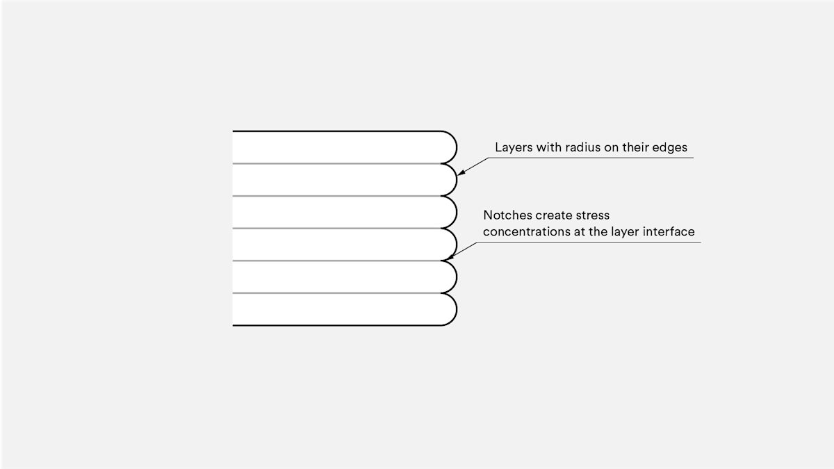
Due to the anisotropic nature of FDM printing, understanding the application of a component and how it is built are critical to the success of a design. FDM components are inherently weaker in one direction due to layer orientation.
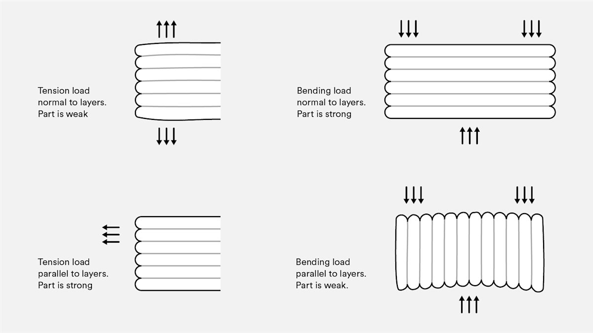
A lack of continuous material paths and the stress concentration created by each layer joint contribute to this weakness. Since the layers are printed as a round-ended rectangle, the joints between each layer are actually small valleys. This creates a stress concentration with a tendency to crack.
FDM materials
The most commonly used 3D FDM materials are summarized in the table below.
| Material | Characteristics |
|---|---|
| ABS | + Good strength + Good temperature resistance - More susceptible to warping |
| PLA | + Excellent visual quality + Easy to print with - Low impact strength |
| Nylon (PA) | + High strength + Excellent wear and chemical resistance - Low humidity resistance |
| PETG | + Food Safe* + Good strength + Easy to print with |
| TPU | + Very flexible - Difficult to print accurately |
| PEI | + Excellent strength to weight + Excellent fire and chemical resistance - High cost |
FDM 3D printing best practices
-
If a bridge exceeds 5mm, sagging or marks from support material can occur. Splitting the design or post-processing can eliminate this issue.
-
For critical vertical-hole diameters, drill after printing to achieve higher accuracy.
-
The addition of support will allow FDM printers to print wall angles greater than 45°.
-
Include a 45° degree chamfer or radius on all edges of an FDM part touching the build plate.
-
For applications with small vertical pins, add a small fillet at the base or consider inserting an off-the-shelf pin into a printed hole instead.
-
Splitting a model, reorienting holes and specifying build direction are all factors that can lower cost, accelerate the printing process and improve a design’s strength and print quality.
Want to learn more about 3D printing? Read our full guide: What is 3D printing?