
What are the most common STL file errors, and how will they affect your ability to export models for 3D printing? While the transition from a digital design to a physical object seems seamless, the underlying geometry can often become ‘broken’ during the export process. Learning to identify and fix STL file errors early is important to ensure your next 3D printing run proceeds without delays or costly manual repairs.
The transition from CAD to STL: Mesh conversion explained
The STL file format is the most commonly used file type in 3D printing. All modern CAD (Computer Aided Design) software allows you to export their native file format into STL.
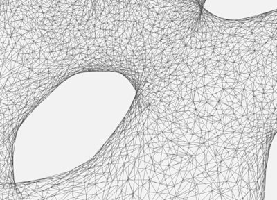
The STL file represents a 3D model by approximating its outer surfaces using multiple triangles. These triangles create a 3D network (mesh) of points, edges, and faces. This mesh defines the internal volume of the model.
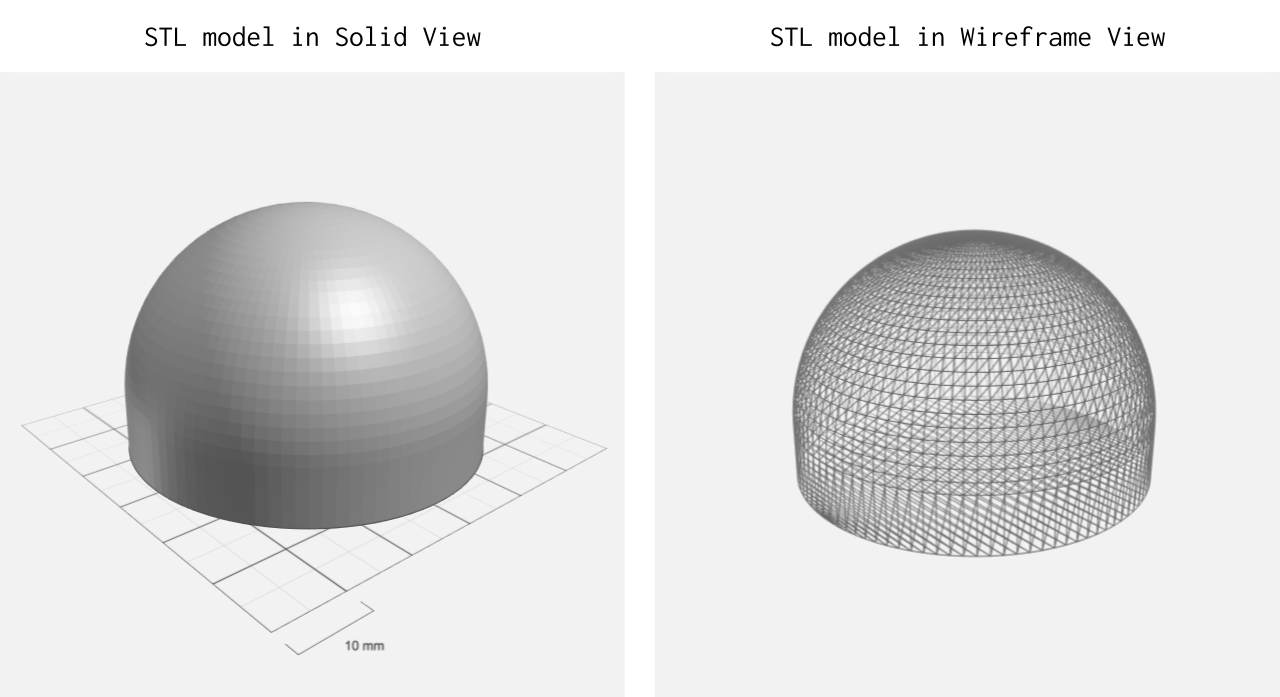
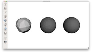
To understand STL errors, it helps to visualize the conversion as a ‘broken mirror’ effect. In your native CAD software, geometry is defined by perfect mathematical curves and splines. However, the STL format doesn't understand curves. It translates these perfect surfaces into a cloud of thousands of flat triangles.
This process, known as tessellation, converts a CAD model into a mesh of interconnected triangles. When the conversion is performed correctly, these triangles align edge-to-edge to create a continuous, watertight surface. If the geometry is not translated accurately, defects such as gaps, overlapping faces, or inverted normals can occur. These errors create an invalid mesh that a 3D printer may be unable to interpret correctly.
We have a detailed step-by-step guide here that explains how to correctly convert your 3D models into STL files.
What happens if you 3D print a faulty STL?
A 3D-printable STL file must be manifold, meaning the geometry is completely watertight and has a clearly defined interior and exterior. If an STL is non-manifold, the slicing software may struggle to interpret the model correctly. Since the slicer generates toolpaths based on cross-sections of a solid volume, ambiguous geometry can result in missing surfaces, unintended gaps, or incorrect infill patterns in the final print.
Beyond the risk of a failed print, a faulty file can impact your bottom line. Most professional 3D printing service providers will decline an order with significant mesh errors or increase the price to account for the manual labor required to repair the file.
On Protolabs Network, we offer handy tools to help you identify errors with your STL files. You can access the Printability Analyser by clicking ‘View in 3D’ in the checkout.
Common STL errors
Most mesh issues fall into a few specific categories. Understanding these helps you assess whether you can perform a quick fix or if you need to return to your CAD environment.
Boundary edges
Boundary edges are identified when certain edges in an STL file are connected to only one face rather than two adjacent faces. This indicates the presence of holes in the geometry, meaning the model does not represent a closed, watertight volume.
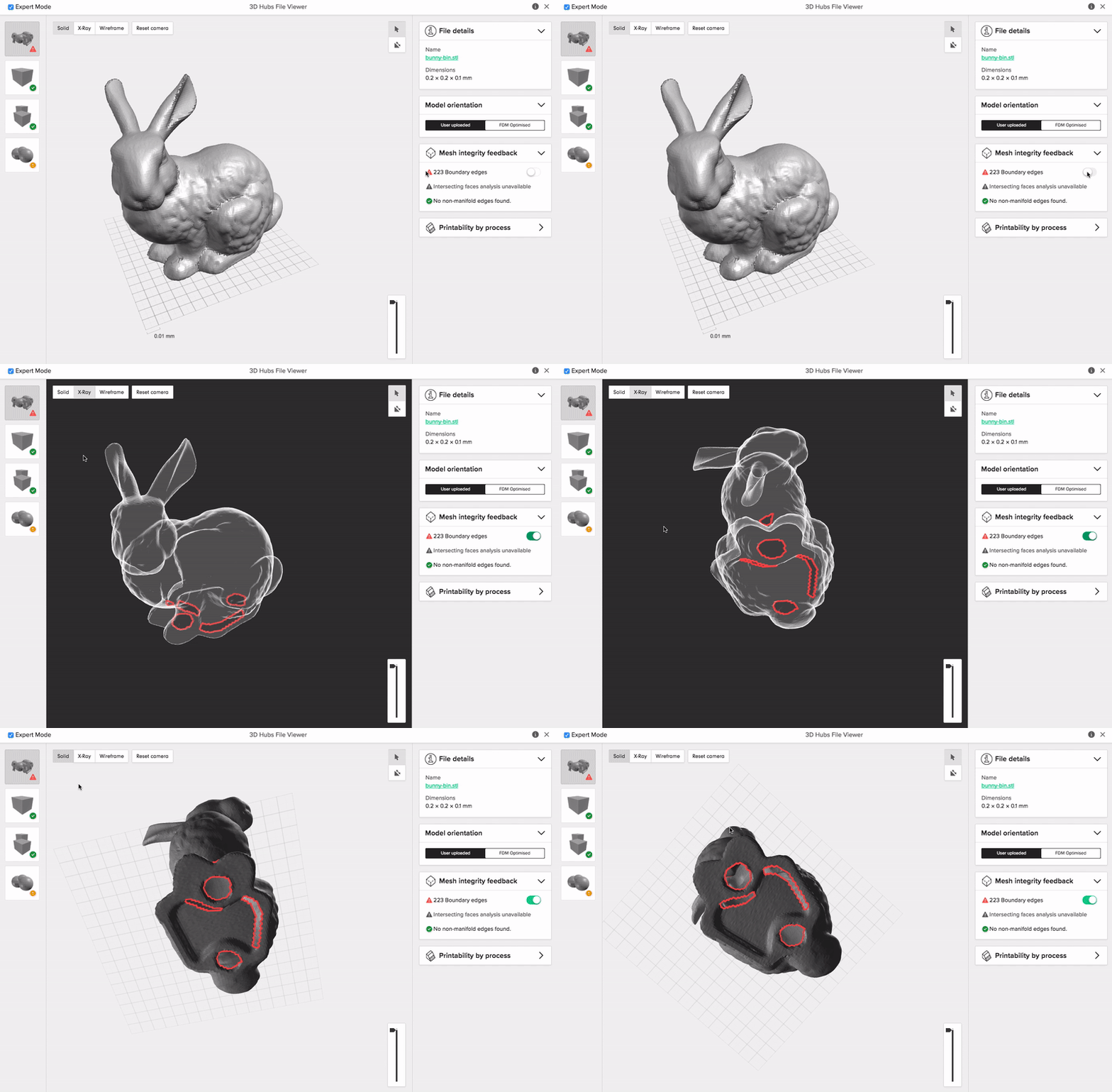
Most modern slicing software can still process STL files with open boundaries. However, ambiguous geometry may be interpreted differently by different slicers, making the final result difficult to predict and potentially inconsistent with the original design intent.
For example, if the open boundary edge is located on a curved surface (for instance, on the side of a cylinder), then the slicing software is likely to fill the void with a flat surface, altering the original design.
| Severity | CAD model modification or STL repair required. |
|---|---|
| Our recommendation | Re-model the areas where the boundary edges were detected in the native CAD software or repair the faulty STL. |
Intersecting faces
Intersecting faces occur when two surfaces collide or occupy the same space, which is a common error when multiple bodies are positioned together without being merged. This creates a major problem for slicing software, which struggles to identify which areas are ‘inside’ the model and which are ‘outside’.
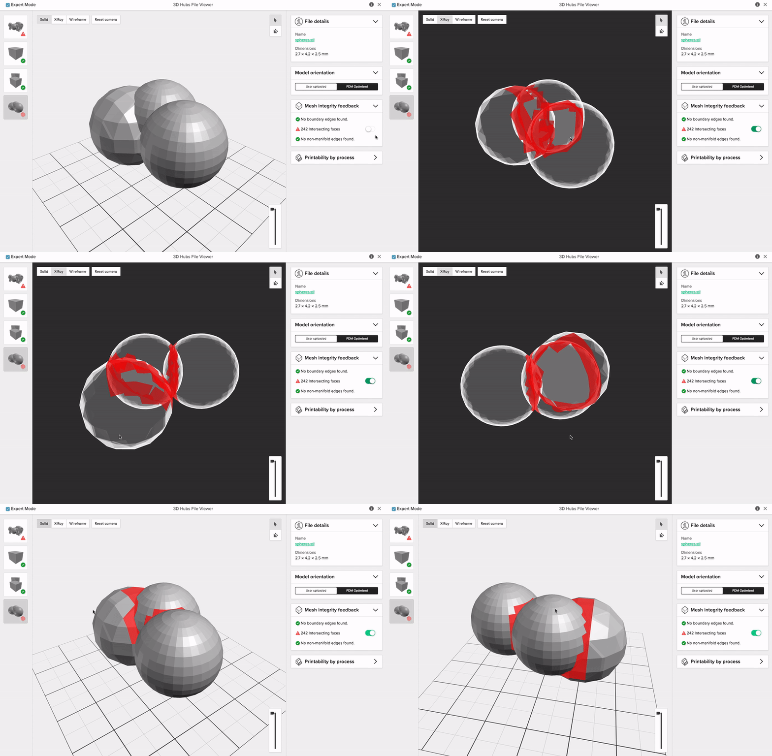
When surfaces overlap this way, it often leads to slicing failures or erratic toolpaths. In some cases, the printer may even try to deposit a double amount of material into the overlapping zone, potentially leading to a nozzle jam or damaging the print head.
While most dedicated repair software can resolve these collisions, success is not always guaranteed. The best design practice, and the one that saves the most effort, is to use a ‘Boolean Union’ to combine all bodies into a single solid within your native CAD software before exporting the STL.
| Severity | CAD model modification or STL repair required. |
|---|---|
| Our recommendation | Combine the bodies into a single solid before exporting them into STL, or repair the faulty STL. |
Non-manifold edges
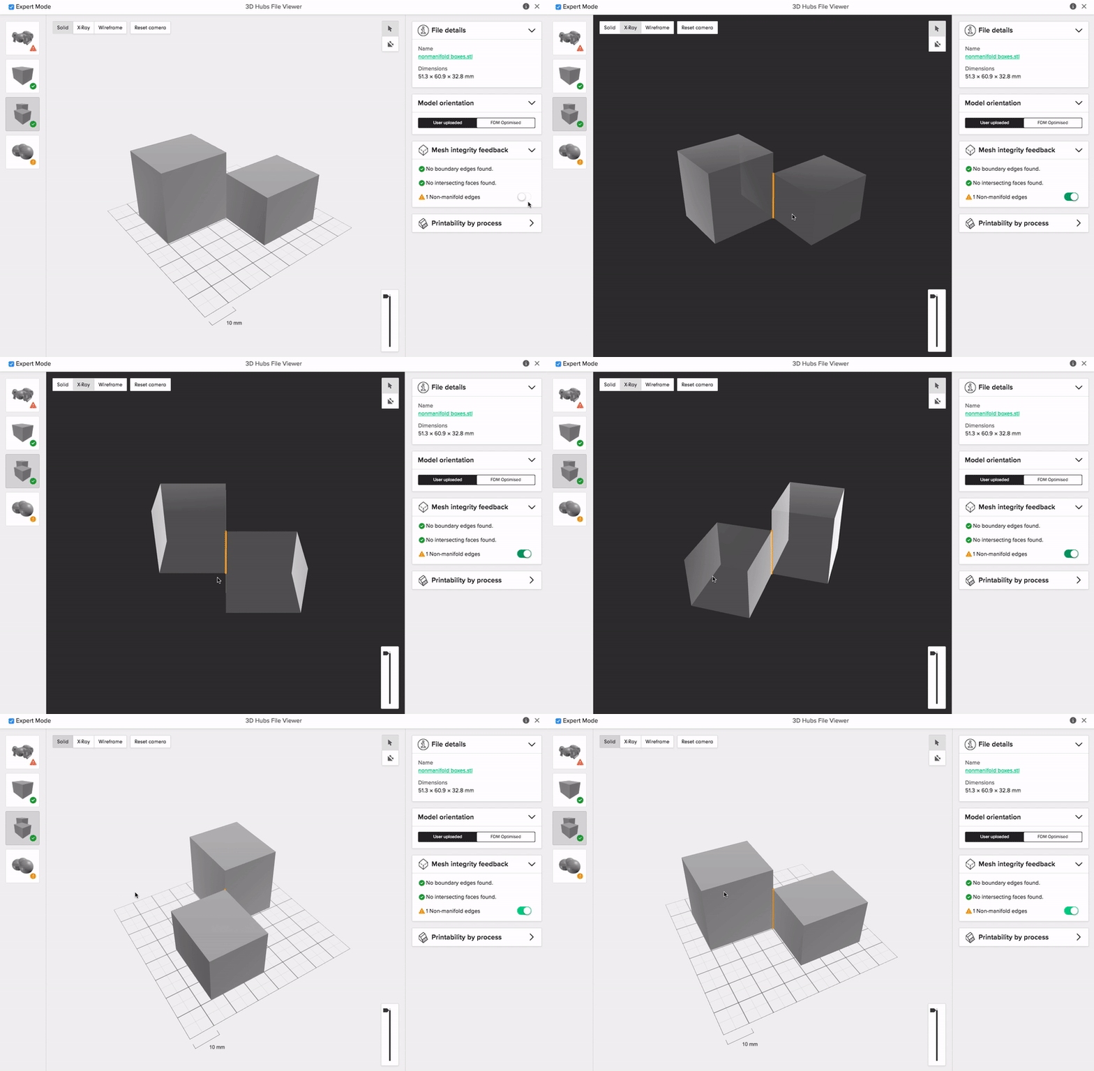
Non-manifold edges occur when more than two faces share the same edge. This error usually appears in two ways: an extra internal surface may split the model, or the same edge may be shared by multiple separate bodies. Although this issue rarely causes major slicing problems, it should still be avoided because it makes the designer’s intent unclear and can lead to unpredictable geometry interpretation.
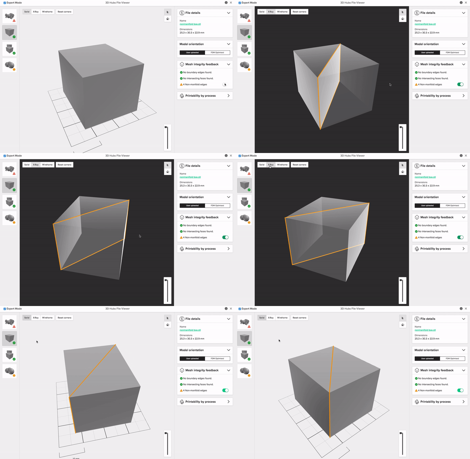
For instance, when an edge is shared by more than one body, it is not certain whether the designer wants these to be connected into a single piece or printed as two objects. To avoid this uncertainty, it is good practice to always add some thickness to the thin sections of your 3D models or increase the clearance between the features that you do not wish to be connected (0.3 mm clearance is usually sufficient). For details on the recommended minimum wall thickness, please refer to the design guidelines of the 3D printing process you are using.
| Severity | CAD model modification recommended. |
|---|---|
| Our recommendation | Examine the faulty edges and alter your design accordingly, adding thickness or clearance where needed. |
Over-refined mesh
A mesh is ‘over-refined’ when the total number of triangles of the STL mesh is larger than required. This won’t lead to any errors during 3D printing, but it will increase the size of the STL file unnecessarily, making it more difficult to handle. Usually, the tiny details that are represented by an over-refined mesh cannot be 3D printed, as they exceed the capabilities of most systems (in terms of accuracy and minimum feature size).
| Severity | Attention needed. |
|---|---|
| Our recommendation | Export using the default setting of your software or by following our guidelines here. |
The 5-step STL repair workflow
When you encounter a ‘dirty’ mesh, follow this systematic approach to fix STL file error issues effectively:
-
Auto-repair: Use a basic repair algorithm to fix simple holes and flipped normals.
-
Separating shells: Identify if your model consists of multiple separate ‘shells’ that should be merged.
-
Closing holes: Manually or automatically cap boundary edges to ensure the mesh is watertight.
-
Resolving overlaps: Use Boolean operations to combine intersecting faces into a single continuous volume.
-
Remeshing: If the mesh is too complex or distorted, use a remeshing tool to redistribute triangles evenly across the surface.
Best free and professional STL repair tools
We recommend these two options for repairing your STL files:
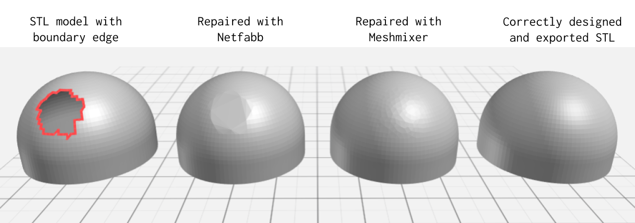
Repair your STL file using a dedicated 3D printing software: Many software solutions exist dedicated to the preparation of STL files for 3D printing. They can repair most STL errors. Popular (and free) examples include Netfabb (using the Repair command) and Meshmixer (using the Inspector command). For quick repairs, 3D Builder is an easy-to-use software for visualizing and repairing STL files and a free online STL repair tool can be found here.
Repair the error in the native CAD software before exporting to STL: In most cases, best results will be achieved when the STL file is correctly designed and exported in the first place and is always the recommended option.
Best practices for error-free exports
The best way to handle STL errors is to prevent them at the source. Always prioritize solving geometry issues in your native CAD software before exporting, as this ensures the underlying mathematics remain intact.
-
Boolean Unions: Combine all separate bodies into one single solid before export to prevent intersecting faces.
-
Binary Format: Choose ‘Binary STL’ rather than ‘ASCII’ to keep file sizes manageable while maintaining high resolution.
-
Check Resolution: Find the balance where curves look smooth but the triangle count remains under one million to avoid unmanageable files.
Before placing your order, use our automated Design for Manufacturing (DFM) tool to identify common STL issues in seconds. Simply upload your file to the Protolabs Network platform, and the system will automatically check for non-manifold edges, holes, and orientation errors, ensuring that your design is production-ready.
Get started
Ready to check your STL file for printability issues? Upload your design for a free, instant quote with automated DFM feedback and mesh error detection
Frequently asked questions
How to fix an STL file?
The most effective way is to use a dedicated repair tool such as 3D Builder or Netfabb. These programs scan the mesh for boundary edges and intersecting faces, then automatically ‘stitch’ the triangles back together to create a manifold solid. If the error is structural, it’s always better to return to your CAD software and merge your solids properly before re-exporting.
How to smooth an STL file?
You can smooth a mesh using a remeshing or brush tool in software such as Meshmixer. These tools redistribute the mesh triangles and soften faceted edges, creating a smoother surface. However, use these with caution, as smoothing can alter the dimensional accuracy of the model and potentially cause fitment issues in mechanical assemblies.
Will repairing an STL file reduce its quality?
In most cases, no. Automated repairs usually just close gaps or remove redundant internal faces. However, if you use a ‘shrink-wrap’ or ‘heavy remesh’ repair method, you might lose some fine detail or sharpen edges as the software simplifies the geometry to make it manifold.
Is it better to fix the STL or the original CAD file?
Always fix the original CAD file if possible. Repairing an STL is like patching a blurry photo - you’re working with an approximation. Fixing the native CAD ensures the mathematical foundation of your part is perfect, resulting in a much cleaner, more reliable STL export.