What is metal 3D printing? The differences between SLM and DMLS

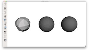
Selective laser melting (SLM) and direct metal laser sintering (DMLS) are metal additive manufacturing processes in the powder bed fusion family. Both use a laser to scan and selectively fuse or melt metal powder particles, building a part layer by layer. In both cases, these materials are granular metal powders.
The differences between SLM and DMLS relate to how particles bond. SLM uses metal powders with a single melting temperature and fully melts the particles, while DMLS uses powders composed of materials with different melting points that fuse at elevated temperatures on a molecular level. In practice, SLM typically produces parts from a single metal, while DMLS produces parts from metal alloys.
While they are technically different, SLM and DMLS are more or less interchangeable for most applications. Both processes produce high-performance, dense metal parts, so your choice should be guided by the required material alloy, as opposed to the specific laser process.

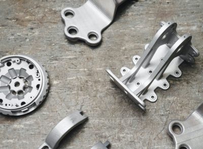
Both SLM and DMLS are used in industrial applications to create end-use engineering components. In this guide, the term metal 3D printing refers to both processes and explains the benefits and limitations of the technology.
Other additive processes can produce dense metal parts, such as electron beam melting (EBM) and ultrasonic additive manufacturing (UAM). Their availability and applications are limited, so they are not covered here.
DMLS is available from Protolabs. Get a quote for metal 3D printed parts via the Protolabs platform. Choose from various production-grade metals, including aluminum, stainless steel, Inconel and titanium.
Explore Metal 3D Printing Capabilities via ProtolabsHow does metal 3D printing work?
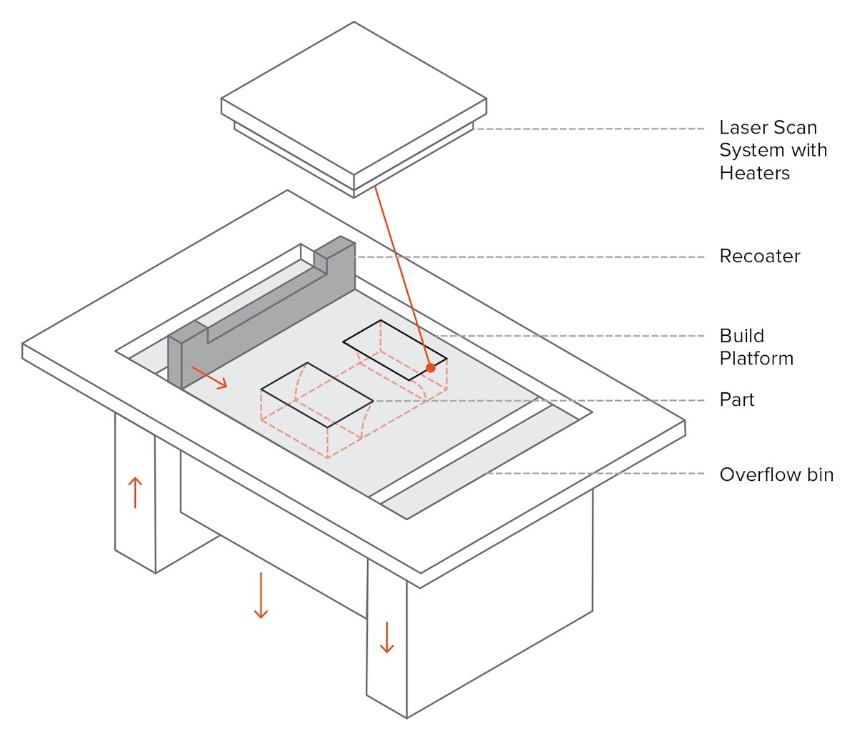
The fabrication process is similar for both SLM and DMLS:
-
The build chamber is purged with an inert gas, such as argon, to minimize oxidation, then heated to the target build temperature.
-
A thin layer of metal powder is spread across the build platform. A high-power laser then scans the component’s cross-section, melting or fusing the powder to form a solid layer.
-
After each scan, the build platform lowers by one layer thickness and the recoater spreads a fresh layer of powder. This process repeats until the part is complete.
When the build finishes, parts are fully surrounded by loose powder. Unlike polymer powder bed fusion (such as SLS printing or MJF), the parts are attached to the build plate with support structures made from the same metal. Support is required to control warping and distortion caused by high processing temperatures.
After the build cools to room temperature, excess powder is removed. Parts are typically heat treated on the build plate to relieve residual stress. Components are then detached from the plate by cutting, machining, or wire EDM and are ready for use or further post processing.
Want to design better parts for 3D print manufacturing?
What are the characteristics of metal 3D printing? Get to know SLM and DMLS
SLM and DMLS printer parameters
In SLM and DMLS, most process parameters are defined by the machine manufacturer. Layer height typically ranges from 20 to 50 microns and depends on powder properties such as flowability, particle size distribution, and particle shape.
A common build size for metal systems is 250 x 150 x 150 mm, with larger platforms available up to 500 x 280 x 360 mm. The dimensional accuracy is approximately ±0.1 mm.
Metal printers support small batch manufacturing. Their throughput is closer to the batch capabilities of FDM or SLA than SLS because parts must be attached to the build plate, which restricts the usable area in the XY direction.
Powder reuse rates are high. Typically less than 5% is wasted. After each build, unused powder is collected, sieved, and replenished with fresh material to reach the required level for the next project.

Layer adhesion
SLM and DMLS metal parts show near isotropic mechanical and thermal properties. As-printed porosity is typically 0.2 to 0.5 percent and is reduced to near zero after thermal processing.
Metal 3D printed parts often exhibit higher strength and hardness, and in some cases greater flexibility compared to parts made with traditional methods. They are, however, more susceptible to fatigue.
For example, when comparing the mechanical properties of AlSi10Mg printed on EOS systems with the A360 die cast alloy, you can see that these materials have similar chemistries with high silicon and magnesium content. The printed parts show superior mechanical properties and more hardness compared to the cast counterpart.
Because the feedstock is granular, the as-built surface roughness Ra is approximately 6 to 10 micrometers. This relatively high roughness contributes to lower fatigue strength.
| AlSi10Mg (3D printing alloy) | A360 (Die cast alloy) | |
|---|---|---|
| Yield Strength (0.2% strain)* | XY: 230 MPa Z: 230 MPa |
165 MPa |
| Tensile Strength* | XY: 345 MPa Z: 350 MPa |
317 MPa |
| Modulus* | XY: 70 GPa Z: 60 GPa |
71 GPa |
| Elongation at break* | XY: 12% Z: 11% |
3.5% |
| Hardness** | 119 HBW | 75 HBW |
| Fatigue Strength± | 97 MPa | 124 MPa |
*Heat treated: annealed at 300 degrees Celsius for 2 hours ± Tested on as-built samples
Support structures & part orientation
Support structures are required in metal powder bed fusion due to the high processing temperature and are typically built in a lattice pattern. Support structures in metal 3D printing serve three functions:
-
Provide a platform for the next layer.
-
Anchor the part to the build plate to limit warping.
-
Act as heat sinks to draw heat from the part and control cooling.
Metal 3D printing supports must dissipate heat and withstand significant thermal stresses during the build process. As a result, they are typically designed as solid metal structures that are firmly bonded to the part. Removing them is far more labor-intensive than in plastic 3D printing and often requires secondary operations such as CNC machining or wire EDM, adding significantly to the overall manufacturing cost.
Parts are mostly oriented at an angle to reduce warping and align strength in critical directions. This increases the amount of support, build time, material waste, and total cost. Warping can also be reduced with randomized scan patterns. This strategy limits residual stress buildup in any direction and produces a characteristic surface texture.
Given the high cost of metal printing, simulations are used to predict part behavior during processing. Topology optimization is used to improve mechanical performance, reduce support requirements, and lower the risk of warping.

Hollow sections & lightweight structures
Unlike polymer powder bed fusion processes such as SLS, large hollow sections are uncommon in metal printing as the internal support structures cannot be removed as easily.
For internal channels larger than Ø 8 mm, diamond or tear drop cross sections are preferred over circular ones, as these do not require internal supports. More design guidelines on SLM and DMLS can be found in this article about metal 3D printing.
As an alternative to hollow sections, parts can be designed with a skin-and-core structure. In this approach, the skin and core are processed using different laser powers and scan speeds, resulting in distinct material properties within the same part. This strategy is particularly beneficial for large solid sections, as it reduces print time and the risk of warping while maintaining high structural stability and good surface quality.
Lattice structures are also widely used to reduce weight, while topology optimization can help engineers to develop highly efficient lightweight geometries. Internal cavities offer some of the greatest opportunities for weight reduction, but they require drainage holes to remove unfused metal powder. Without these outlets, trapped powder adds unnecessary weight and increases material costs, as the expensive alloy cannot be recovered and reused.
What are the common materials for 3D metal printing?
SLM and DMLS can produce parts from a wide range of metals and metal alloys, including aluminum, stainless steel, titanium, cobalt chrome, and Inconel. These materials cover most industrial applications, from aerospace to medical. Precious metals such as gold, platinum, palladium, and silver can also be processed, primarily for jewelry.
A key strength of metal 3D printing is its compatibility with high strength materials, including nickel and cobalt chrome superalloys that are otherwise difficult to process with traditional methods. Cost and time can be reduced by printing a near net shape and then post processing to achieve the required surface finish.
| Material | Key properties |
|---|---|
| Aluminium alloys | Good mechanical & thermal properties; Low density; Good electrical conductivity; Low hardness |
| Stainless steel & tool steel | High wear resistance; Great hardness; Good ductility and weldability |
| Titanium alloys | Corrosion resistance; Excellent strength-to-weight ratio; Low thermal expansion; Biocompatible |
| Cobalt-Chrome superalloys | Excellent wear & corrosion resistance; Great properties at elevated temperatures; Very high hardness; Biocompatible |
| Nickel superalloys (Inconel) | Excellent mechanical properties; High corrosion resistance; Temperature resistant up to 1200 degrees Celsius; Used in extreme environments |
| Precious metals | Used in jewelry making; Not widely available |
Post-processing methods for metal 3D printing
Post-processing in metal 3D printing is essential for improving the mechanical properties, dimensional accuracy, and surface finish of SLM and DMLS parts used in engineering applications. Typical post-processing steps include removing loose powder and support structures. Heat treatments, such as thermal annealing, are commonly applied to relieve residual stresses, improve material performance, and ensure consistent part quality.
CNC machining is used for dimension-critical features, such as holes and threads, in order to meet tight tolerances. Media blasting, metal plating, polishing, and micro machining improve surface quality and can increase fatigue strength.

What are the benefits & limitations of metal 3D printing?
-
Metal 3D printing produces complex, custom parts with geometries that traditional manufacturing cannot achieve.
-
Parts can be topologically optimized to improve performance while reducing weight and part count in an assembly.
-
Printed parts offer excellent mechanical properties, and the material range includes difficult-to-process superalloys.
-
Material and manufacturing costs are high, so these processes are not suitable for parts that can be made economically with conventional methods.
-
Build size is limited because precise process control and stable conditions are required.
Existing designs may not be suitable for metal 3D printing and may need modification. The main characteristics of SLM and DMLS systems are summarized in the table below.
| Metal 3D printing (SLM / DMLS) | |
|---|---|
| Materials | Metals & metal alloys (aluminum, steel, titanium) |
| Dimensional accuracy | ± 0.1 mm |
| Typical build size | 250 × 150 × 150 mm (up to 500 × 280 × 360 mm) |
| Common layer thickness | 20–50 μm |
| Support structures | Always required |
Get started
Ready to evaluate metal 3D printing for your part? Upload your design for a free, instant quote with material recommendations and DFM feedback.
Frequently asked questions
What can you manufacture with metal 3D printing?
Metal 3D printing is particularly well suited to the production of complex, custom metal components that would be difficult, time-consuming, or cost-prohibitive to manufacture using traditional manufacturing processes.
Is metal 3D printing expensive?
Metal 3D printing is more expensive than most additive manufacturing processes. Stainless steel 316L powder can have high costs.
How do you reduce the cost of metal 3D printing?
Cost reduction primarily comes from minimizing material usage and shortening build times. The most effective strategies are reducing part volume and designing components to minimize or eliminate support structures wherever possible.
What is metal 3D printing commonly used for?
Metal 3D printing is commonly used for prototyping in production-grade materials and for producing functional, end-use parts. It is also selected for manufacturing complex geometries and for consolidating multiple metal components into fewer parts within an assembly.
Are support structures required for metal 3D printing?
Yes. Support structures are required in metal 3D printing due to the high processing temperature. Supports are typically built in a lattice pattern.
What are the best alternatives for metal 3D printing?
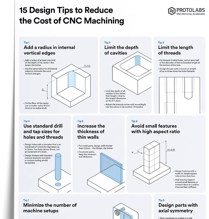
Metal 3D printing produces complex and robust parts, but the cost can be high. For many complex geometries, 5-axis CNC machining is a strong alternative for engineers sourcing production parts.
Can you 3D print aluminum parts?
Yes. Aluminum is widely used in metal 3D printing due to its strength-to-weight ratio and strong thermal properties. Common applications include automotive, medical, and aerospace components.
Can you 3D print with stainless steel?
Yes. Stainless steel is used in SLM and DMLS to produce complex, high-pressure components for engineering applications.