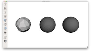
What’s inside an FDM 3D-printed part matters just as much as what’s on the outside. Cut one open, and instead of a solid block, you’ll likely find a patterned internal structure. Known as infill, it helps balance strength, weight, and material use inside the outer shell. By changing its pattern and density, you can tune how a part performs without changing its external shape.
Infill is most common in FDM printing, but other 3D printing processes can also use internal structures such as hollow sections or lattices to reduce weight and material use.
Standard infill is usually defined in the slicer rather than modeled directly in CAD, but the choices you make in your design, like wall thickness, top surface area, and load paths determine which infill settings work best. This guide covers the key infill settings, the most common patterns, and how to match them to your application.
Key parameters of infill settings
Three main settings influence your infill: density, pattern geometry, and overlap. Most slicers let you tweak these, and knowing how they work together is key for a solid print. For more on how these tie into wall thickness, check out this guide on shell and infill parameters.
-
Infill density (0-100%): How much of the inside is filled with material. More density usually increases internal support and can improve strength, but it also leads to longer print times.
-
Pattern geometry: The shape of the repeating structure inside. Different shapes handle stress differently.
-
Infill overlap: How much the infill overlaps with the inner walls. Too little weakens the bond, while too much causes over-extrusion.
Understanding infill density
Density is often one of the most important infill settings for part performance. It can directly affect print time and material use, so it’s worth choosing carefully.
-
0-15%: Best for decorative parts and visual prototypes. This range prints quickly and uses very little material but provides minimal internal support.
-
15-50%: The typical range for most prototypes. Around 20% works well for form-and-fit parts, while 40–50% gives you more stiffness.
-
50-100%: Better for functional parts under heavier load. At 100%, the part is fully solid, which increases strength but also adds weight, time, and cost. For many engineers, 70–80% is enough to get close to solid-part performance.
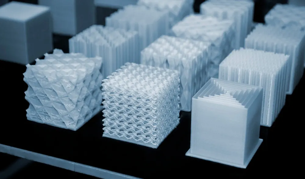
Common 3D printing infill patterns
Every infill pattern has its own way of handling stress. Some are better for everyday prototyping, while others are designed for faster prints, stronger parts, or a more decorative finish.
| Pattern | Description | Best known for |
|---|---|---|
| Grid | A simple, widely used all-purpose pattern. | A balanced mix of strength, speed, and ease of printing. |
| Honeycomb | A hexagonal structure that provides solid support without adding as much material as a dense part. | A good strength-to-weight ratio. |
| Gyroid | A smooth, continuous 3D structure that distributes loads in multiple directions. | Near-isotropic strength and flexibility. |
| Lines | A basic pattern with minimal travel. | Faster prints and simple prototypes. |
| Lightning | A sparse pattern that places material only where support is needed. | Lower material use and shorter print times. |
| Tri-Hexagon | A more rigid pattern designed for stronger internal support. | High strength. |
| Octet | A strong 3D lattice that adds structural support. | Strength and stiffness. |
| Concentric | A pattern that follows the shape of the part. | Visual effect in translucent or thin-walled designs. |
The best infill pattern depends on the part’s requirements. Some patterns are better suited for everyday prototyping, while others are designed for strength, lower material use, or a specific look.
Patterns for speed vs. strength
Some infill patterns are built for speed, while others put more emphasis on strength. Patterns like Lines or Lightning print faster because they reduce travel and use less material, so they work well for visual prototypes or lightweight parts.
Patterns like Tri-Hexagon or Octet take longer to print, but they provide stronger internal support, so they are often used for functional parts and high-stress applications where stiffness and load-bearing performance are higher priorities than print speed.
Print orientation also comes into play. Aligning the strongest infill axis with the main load direction boosts performance without upping density.

Why infill choice matters for part quality
Infill affects both part strength and print quality. The internal structure helps the part resist force and supports the top layers as they print.
A stronger infill can help improve tensile and shear strength by giving the part more support against pulling and sliding forces. It can also help the outer shell stay more stable under load.
Infill helps to prevent defects like top-surface sagging as well. When the structure underneath is too sparse, the top layers may not have enough support, which can cause drooping or pillowing. A denser or better-supported infill gives those layers a stronger base and can lead to a smoother finish.
Advanced infill optimization techniques
Modern slicers give engineers more ways to apply infill strategically instead of relying on the same density throughout a part. That can be especially useful in industrial 3D printing, where strength, weight, and material use all need to be balanced carefully.
Variable (or adaptive) infill changes density depending on the shape of the part, adding material where more strength or support is needed and using less where it isn’t. Gradient infill shifts density more gradually, often with denser outer regions and a lighter core.
Both approaches can improve the strength-to-weight ratio by putting material where it does the most work.
Troubleshooting infill-related issues
Even with solid infill settings, problems can occur if your printer isn't calibrated right or if the pattern doesn't mesh well with the part's geometry.
-
Poor layer adhesion: Try increasing infill overlap slightly and check the nozzle temperature.
-
Gaps in the lattice: Usually caused byunder-extrusion. Look for clogs, worn nozzles, or incorrect filament diameter settings.
-
Nozzle clogging: At higher densities, some patterns route the nozzle over already-deposited lines, which can cause material build-up and clogging. Switching from Grid to Gyroid at high densities often fixes this, as Gyroid’s continuous geometry steers clear of sharp crossovers.
-
Weak infill-to-wall bonding: Increase overlap or add an extra wall. For parts withthin walls, wall count and overlap are especially critical.
Aesthetics and visual impact of infill
Infill is usually chosen for structural reasons, but in some prints, it can also contribute to the overall appearance.
Patterns like Concentric, with its repeated contour-like rings, or Gyroid, with its smooth, flowing lattice, can create interesting visual effects, especially with translucent filaments or thin-walled parts where the internal structure shows through. Instead of hiding the infill, these patterns can add texture, depth, and detail.
This can be useful for lamps, shades, display pieces or other parts where form is just as important as function.
When infill is meant to be seen, wall thickness andsurface finishing also shape the final look. In thin-walled or single-walled designs, a bold pattern can turn a functional infill into a design feature.
How to choose the right infill for your project
Choosing infill comes down to what the part needs to do. A lightweight display model and a functional prototype under load need very different settings.
| If the part needs to… | Recommended density | Recommended pattern |
|---|---|---|
| Look good on a shelf | 10–15% | Lines or Lightning |
| Pass a form-and-fit check | 20–30% | Grid or Cubic |
| Handle moderate mechanical loads | 40–50% | Honeycomb or Gyroid |
| Survive repeated stress cycles | 60–80% | Gyroid or Octet |
| Bear heavy structural loads | 80–100% | Octet or solid fill |
Get started
Ready to put your infill settings to work? Upload your design for an instant FDM quote.
Frequently asked questions
What is the best infill percentage for 3D printing?
There is no single best value: 20% works for most prototypes, 50% for functional parts, and 80–100% for heavy-load applications.
Does infill pattern affect print time?
Yes. Simple patterns like Lines print faster than Honeycomb or Octet, and higher density increases time roughly in proportion to the added material.
What infill pattern is strongest?
Gyroid and Octet are among the strongest commonly used patterns. Gyroid provides more even strength in multiple directions, while Octet performs well in parts that need high stiffness and support.