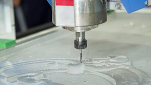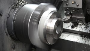

Precision is more than a marketing term. For CNC-specialists, it is the technical capability to consistently hit tolerances of 0.01 millimeters or tighter. Achieving this level of accuracy requires more than high-end equipment. It demands a deep understanding of thermal stability, tool deflection, and material harmonics.
This guide explores the fundamental principles of precision CNC machining. We examine the critical variables that allow engineers to push the boundaries of dimensional accuracy and surface integrity for mission-critical components.
In industries like the aerospace sector, medical devices, or high-performance automotive - mastering these variables is the difference between a functional prototype and a failed assembly.
What defines precision in CNC machining?
True precision is the result of a controlled synergy between the machine, the tooling, and the environment. Achieving tolerances of 0.01 millimeters is impossible if any of these variables are unstable.
Machine rigidity and tooling quality form the foundation. A rigid frame dampens vibrations that cause 'chatter', while high-quality tools resist tool deflection to ensure the cutting edge remains exactly on path.
However, even the most rigid machine cannot overcome poor thermal stability. Because metals expand and contract with temperature shifts, a workshop without climate control introduces constant dimensional drift. For high-accuracy components, a change of just a few degrees can cause a part to expand beyond its specified limits.
Without a temperature-controlled environment to stabilize the material and the equipment, 'precise' machining remains a moving target.

The pillars of high-accuracy manufacturing
True precision is the result of a controlled synergy between the machine, the tooling, and the environment. Achieving tolerances of 0.01 millimeters is impossible if any of these variables are unstable. These three pillars must work together to ensure a predictable and repeatable process.
Machine rigidity and tooling quality form the foundation of the system. A rigid machine frame is important to damp vibrations that cause 'chatter', which can ruin both surface finish and dimensional accuracy. High-quality tools are equally important because they resist tool deflection. This ensures the cutting edge remains exactly on the path dictated by the code, even when under heavy load.
However, even the most rigid machine cannot overcome poor thermal stability. Because metals expand and contract with temperature shifts, a workshop without climate control introduces constant dimensional drift.
For high-accuracy components, a change of just a few degrees can cause a part to expand beyond its specified limits. Without a temperature-controlled environment to stabilize the material and the equipment, 'precise' machining remains a moving target.
Geometric dimensioning and tolerancing (GD&T)
To maintain the highest level of accuracy, precision machining must also account for complex geometric relationships. Engineering drawings for high-accuracy components often rely on Geometric Dimensioning and Tolerancing (GD&T) symbols to define more than just linear dimensions.
Our process is designed to interpret and meet rigorous requirements for symbols such as positions of runout, parallelism, and true position.
These callouts ensure that features like holes and bores are not just the right size, but are also perfectly aligned and oriented relative to the rest of the part. Mastering these complex geometric constraints is important for ensuring that precision components fit and function correctly within a larger assembly.
Multi-axis machining (3, 4, and 5-axis)
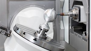
One of the most effective ways to maintain extreme accuracy is through 5-axis machining. This technology allows for the completion of complex geometries in a single setup, which is a major advantage for precision engineering.
Every time a part is moved or re-fixtured, you risk losing a few micrometres of accuracy. These small errors occur because it is nearly impossible to align a part perfectly twice.
By using a 5-axis setup, the machine can access almost every angle of the component without the need for manual intervention. This eliminates 'stack-up errors' from multiple setups and ensures that the finished part stays within the tightest of tolerances.
Material selection for dimensional stability
Material selection is a critical variable in precision engineering as not every metal or plastic behaves predictably under the cutter. Aluminum is widely favored for high-accuracy components because it is exceptionally stable and maintains its dimensions well after material is removed.
In contrast, other materials present significant challenges for tight tolerances. High-nickel alloys such as Inconel are prone to internal stresses that can cause the part to deform or 'creep' once it is released from the machine fixtures. Similarly, many plastics are sensitive to the heat generated during the machining, leading to post-machining expansion or warping.
Understanding these material-specific behaviors is important for engineers to ensure that a part designed at 0.01 millimeters actually stays within that range after it leaves the shop floor.
Design for precision: Reducing tool deflection
The most advanced computer numerical control machine cannot compensate for poor part geometry. Designing for precision therefore requires a deep understanding of how cutting forces affect the tool and the workpiece.
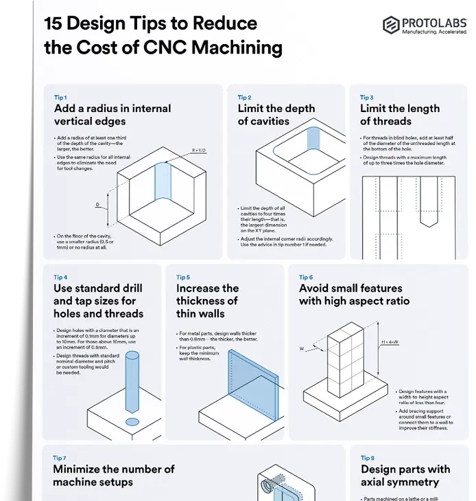
For instance, deep pockets require long cutting tools that are prone to tool deflection. This bending leads to tapered walls and dimensional errors, so engineers should limit pocket depth to four times the tool diameter to maintain maximum accuracy.
Similarly, features like thin walls (under 0.5 millimeters) lack the rigidity to withstand cutting forces. These walls often vibrate, which ruins the surface finish and makes it nearly impossible to hold a tolerance of plus or minus 0.01 millimeters. By optimizing these geometries, you ensure the part remains stable enough to support high-precision results.
Inspection and metrology: Verifying the microns
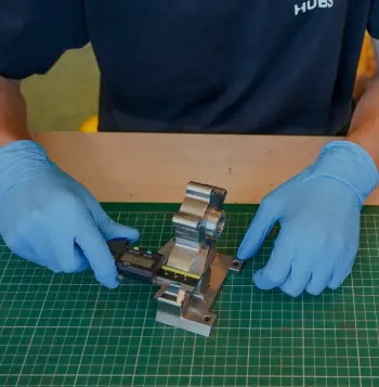
High-accuracy components require rigorous verification to ensure that they meet the specified tolerances.
The Coordinate Measuring Machine (CMM) is the industry standard for validating complex three-dimensional geometries by mapping a part's surface coordinates with extreme precision.
For components with small or intricate profiles, optical comparators project a magnified silhouette of the component on to a screen, allowing for a direct visual comparison against a master template.
To measure ultra-precise bore diameters, air gauging is used. This non-contact method measures the backpressure of airflow between a sensing probe and the bore wall, detecting deviations that traditional mechanical gauges might miss.
Surface finish and its impact on tolerances
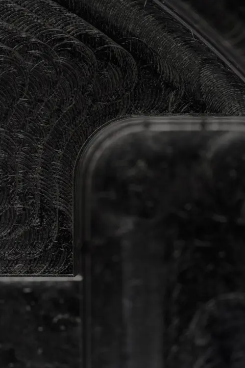
Achieving tight tolerances is inextricably linked to the surface quality of the machined components. A rough surface with a high roughness average (Ra) makes it impossible to measure a tight tolerance accurately.
The measuring probe or sensor will bounce across the microscopic peaks and valleys of the material rather than across a consistent plane. To ensure repeatable and reliable measurements, precision components typically require an as-machined finish of 0.8 micrometers Ra or better.
This level of smoothness provides the stable reference surface necessary for verifying dimensions within a few microns. This ensures that the final components perform exactly as intended in high-precision assemblies.
Get started
Do you want to verify your precision requirements? Achieving the right Ra value is vital for accurate measurement. Upload your CAD file for an interactive quote and a detailed design analysis to ensure your components meet every specification.
Frequently asked questions
Why does precision machining cost more?
The higher cost of precision machining is a result of the specialized requirements needed to hold extreme accuracies.
This process costs more because it requires slower feed rates to maintain stability and more frequent tool changes to ensure the constant sharpness of the cutting edge.
Furthermore, the production of these components relies on specialized fixturing to prevent movement. This must take place in climate-controlled environments to eliminate dimensional changes caused by thermal expansion.
What is the difference between accuracy and precision in CNC?
In computer numerical control, it is important to understand the distinction between accuracy and precision. Accuracy refers to how close a specific measurement is to the true or nominal value defined in the design.
Precision, which is often called repeatability, describes how consistently the machine can hit that same spot over a production run of one thousand components. A precise machine can be calibrated to become accurate. An imprecise machine is useless for high-volume production because it fails to provide consistent results.
How does material hardness affect precision machining?
The hardness of a material significantly impacts the behavior of components during the manufacturing process. Harder materials, such as Stainless 17-4 or Titanium, are often less prone to ‘gumming’ than softer metals, but they cause much faster tool wear.
To achieve the highest levels of accuracy, hard milling is frequently used. This involves machining the material after it has undergone heat treatment. Hard milling is the best way to ensure precision, for components that might warp during traditional heat-treat cycles.
Why is setup reduction critical for tight tolerances?
Setup reduction is critical for maintaining tight tolerances because every time a part is moved to a new fixture, a small locating error is introduced. In manufacturing, these separate stages are often referred to as Operation 10 (Op 10) and Operation 20 (Op 20).
The first operation establishes the initial features, and the second requires the component to be flipped or moved to a new position. By using five-axis machines or specialized tombstone fixtures, more features can be machined in a single setup. This approach eliminates the cumulative errors caused by re-fixturing and significantly increases the true position and overall accuracy of the finished components.