Deciding between 3-axis and 5-axis CNC machining is often a balance between part complexity, precision, and your total production budget. 3-axis machining is the industry standard for cost-effective, straightforward geometries. However, 5-axis technology has redefined what’s possible for intricate aerospace and medical components.
Understanding the key differences in spindle movement and workpiece orientation is important for any engineer looking to optimize their workflow. We break down the specific benefits of each method. This helps you to choose the right setup to reduce setups, improve surface finishes, and hit your deadlines.
Basics of 3 axis and 5 axis machine movement
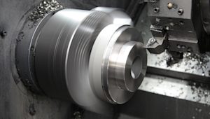
At the core of CNC machining lies the coordinate system that defines tool movement. In a 3-axis setup, the cutting tool moves along the linear X, Y, and Z axes. This configuration is ideal for parts where you only need to reach a single face at a time.
The workpiece remains stationary on the machine bed, limiting the tool to a vertical or horizontal approach. While efficient for simple geometries, it requires manual intervention for any features located on the sides or underside of the part.
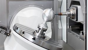
5-axis machining introduces two additional rotary axes, typically referred to as the A-axis and B-axis. These axes allow the tool or the table to tilt and rotate during the cutting process.
In a trunnion-style machine, the table rotates, whereas in a swivel-head machine, the spindle itself tilts. These complex kinematics enable the spindle to approach the part from virtually any angle. This maintains optimal tool engagement, ensures a constant chip load, and eliminates the need for multiple manual setups.
map[fields:map[description:map[en-US:cnc-5-axis-3 2 milling] file:map[] title:map[en-US:cnc-5-axis-3 2 milling]] metadata:map[concepts:[] tags:[]] sys:map[createdAt:2026-05-12T13:31:43.975Z environment:map[sys:map[id:master linkType:Environment type:Link]] id:4b7jTbFD53Q6VWy1ZmLWu1 publishedVersion:4 revision:1 space:map[sys:map[id:q2hzfkp3j57e linkType:Space type:Link]] type:Asset updatedAt:2026-05-12T13:31:43.975Z]]Accuracy, surface finish, and tolerance differences
One of the biggest hurdles in 3-axis machining is the constant need for manual flips to reach different faces. Every time you move a part, you risk alignment errors that push your parts out of tolerance.
5-axis machining solves this by allowing the tool to reach almost every surface in a single setup. By rotating the part or the spindle, you can use shorter and more rigid cutting tools that reduce vibration and deflection. This approach not only maintains tighter precision limits, but also significantly reduces the total labor required for complex geometries.
Part geometry
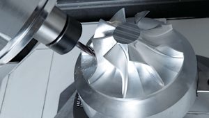
When your design includes undercuts or complex features on multiple faces, 3-axis machines often hit a wall. You would typically need custom fixtures or several manual rotations to reach those hidden geometries, which adds time and cost. 5-axis machining provides superior accessibility by tilting the workpiece to expose those hard-to-reach areas directly to the spindle.
This allows for seamless multiface machining without the risk of repositioning errors. By simplifying the approach to undercuts, you design more intricate parts without worrying about the practical limitations of traditional tool paths.
Setup time, fixturing, and programming complexity
While 5-axis machining reduces physical setup time, it shifts much of the labor to the digital phase. Preparing a 5-axis job requires significant CAM effort, as programmers must define complex tool paths and simulate movements to avoid collisions.
However, the investment pays off on the shop floor. You often eliminate the need for the expensive custom fixtures that are required to hold parts at awkward angles in a 3-axis mill. By consolidating operations into a single setup, you minimize manual handling. This ensures that the relationship between features on different faces remains highly accurate.

Cost drivers for choosing between 3 axis and 5 axis
3-axis machines generally have lower hourly rates because the equipment is less expensive and easier to operate. However, 5-axis machines often justify their higher cost by reducing total cycle time.
Because 5-axis milling keeps the tool at an optimal angle, you experience less tool wear and better chip evacuation. This prevents the heat buildup that leads to premature tool failure.
Additionally, fewer manual setups mean fewer chances for human error. By eliminating repositioning mistakes, you significantly reduce the risk of wasted material on complex parts.
Choosing between 3 axis 5 axis for your parts
Choosing the right machine depends on a few critical factors. If your geometry is flat or only requires features on one face, 3-axis is the most budget-friendly choice. For complex, multi-sided parts, 5-axis becomes more efficient despite the higher hourly rate.
Consider your production volume as well. High-volume runs often benefit from the speed of 5-axis setups, while low-volume, simple parts favor 3-axis simplicity. Always weigh the cost of custom fixtures against the added programming time.
Get an instant quote
Are you ready to optimize your production? Upload your CAD files to Protolabs Network for an instant quote and expert DfM feedback.
Frequently asked questions
What is the difference between 3-axis and 5-axis CNC machining?
3-axis CNC machining moves the cutting tool along the X, Y, and Z axes, while 5-axis machining adds two rotary axes that allow the tool or part to tilt and rotate during machining.
When should you use 3-axis CNC machining?
3-axis machining is best suited for simpler parts that only require machining on a single face or straightforward geometries with fewer complex features.
What are the advantages of 5-axis machining?
5-axis machining allows complex geometries to be machined in fewer setups, improves surface finish quality, reduces repositioning errors, and enables access to difficult-to-reach features.
Is 5-axis machining more accurate than 3-axis machining?
In many cases, yes. Because 5-axis machining reduces the need for manual repositioning, it helps maintain tighter tolerances and minimizes alignment errors between multiple faces.
Why is 5-axis machining more expensive?
5-axis machines are more costly due to their advanced mechanics, programming complexity, and higher equipment costs. However, they can reduce total production time and labor for complex parts.
Can 5-axis machining reduce setup time?
Yes. Although the programming is more complex, 5-axis machining can significantly reduce physical setup time by machining multiple faces in a single operation.
What industries commonly use 5-axis CNC machining?
Industries such as aerospace, medical, automotive, and energy commonly use 5-axis machining for high-precision and complex components.
Do 5-axis machines improve surface finish quality?
Yes. By maintaining optimal tool angles and using shorter cutting tools, 5-axis machining can reduce vibration and improve surface finish quality.
Is 3-axis machining more cost-effective for simple parts?
Yes. For flat or less complex parts, 3-axis machining is typically the more economical option because of lower machine and programming costs.
How do you choose between 3-axis and 5-axis machining?
The choice depends on part complexity, required tolerances, production volume, surface finish requirements, and overall manufacturing budget.