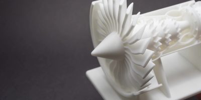
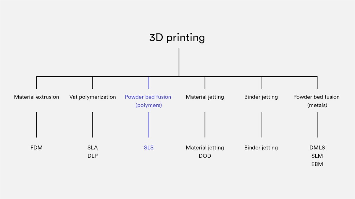
Selective Laser Sintering (SLS) falls under the powder bed fusion category. In the SLS 3D printing process, a laser selectively sinters particles of thermoplastic polymer powder, fusing them together layer by layer to create a solid, functional part. These granular materials offer excellent mechanical properties, making them a staple in industrial manufacturing.
One major advantage of SLS is its versatility. It’s an ideal alternative to injection molding when you want to avoid the high upfront tooling costs. SLS is particularly cost-effective for producing durable components in low to mid volumes, typically fewer than 1,000 units, allowing you to test fit and performance before investing in expensive production tooling.
How does SLS 3D printing work?
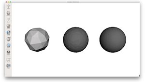
SLS 3D printing engineered for industrial performance relies on a high-powered laser to selectively sinter polymer powder particles, fusing them into a solid mass. Unlike extrusion-based methods, the SLS process scans and sinters the entire cross-section of each layer, which results in exceptionally strong, fully solid parts with near-isotropic properties.
The journey from powder to part begins with pre-heating. The machine heats the powder reservoir and the entire build area to a temperature just below the polymer's melting point. This minimizes the laser energy required for fusion and prevents the part from warping due to sudden temperature shifts. Once stabilized, the layering phase begins: a precision re-coating blade sweeps across the build platform, spreading a thin, perfectly even layer of powder.
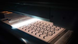
The core of the operation is the laser sintering stage. A CO₂ laser traces the geometry of the specific layer, bonding the particles together precisely where outlined by the digital design. After a layer is completed, the platform lowers slightly, and the process repeats layer-by-layer until the entire volume is formed.
Crucial to the part's success is the cooling phase. Because the build chamber is kept at high temperatures, the ‘powder cake’ must cool down slowly and uniformly, a step that can take up to 12 hours, to ensure dimensional stability.
Finally, the part enters post-processing. At this stage, the component is still encased in a block of unsintered powder. Technicians remove this excess material using compressed air or media blasting leaving behind a functional part that is ready for immediate use or further aesthetic finishing.
A brief history: From industrial giants to benchtop systems
For decades, SLS was the exclusive domain of large-scale industrial facilities. Machines were massive and required specialized infrastructure. The expiration of key patents in around 2014 however sparked a change. Today, the market has expanded to include accessible, benchtop industrial printers.
These smaller systems maintain the high-performance standards of their predecessors but allow smaller firms to bring industrial-grade Nylon printing in-house, significantly shortening the bridge between a digital concept and a physical part.
The SLS hardware ecosystem
The ‘brain’ of a modern SLS printer is its CO₂ laser, but its heart is its thermal management system. Because the powder is heated almost to its melting point before the laser even fires, the machine must maintain an incredibly stable environment. In high-end systems, temperature control is managed within a tight window of ±2°C. Even a minor fluctuation can lead to ‘curling’ or failed layer adhesion, making thermal precision the most critical factor in SLS hardware.
No need for support structures
The absolute primary USP (Unique Selling Point) of SLS is that it requires no support structures. In other technologies, you must design sacrificial scaffolds to hold up overhangs. In SLS, the part is submerged in a bed of unsintered powder at all times. This ‘natural scaffold’ supports every feature, allowing for intricate internal geometries, interlocking parts, and complex lattices that are impossible to manufacture with any other method.
Layer adhesion
One of the reasons engineers specify SLS for functional testing is its near-isotropic mechanical properties. Unlike FDM parts, which are significantly weaker in the Z-axis, SLS parts have excellent layer bonding. The sintering process ensures that the strength in the X, Y, and Z axes is almost uniform.
However, it is important to note that while SLS parts (specifically PA 12) offer great tensile strength, they are slightly more brittle than their injection-molded counterparts. This is due to the internal porosity inherent in the sintering process, where tiny microscopic gaps remain between the fused particles.
| X-Y direction | Z direction | Bulk PA12 | |
|---|---|---|---|
| Tensile Strength | 48 MPa | 42 MPa | 35–55 MPa |
| Tensile Modulus | 1650 MPa | 1650 MPa | 1270–2600 MPa |
| Elongation at break | 18% | 4% | 120–300% |
Shrinkage and Warping
Managing thermal dynamics is essential for SLS success. During the cooling phase, SLS parts typically shrink by 3% to 3.5%. While build software automatically compensates for this by scaling the model, internal stress remains a risk, especially for large, flat surfaces prone to warping.
To minimize distortion, you can implement several strategic design adjustments. Orienting flat features vertically reduces the cross-sectional area being sintered at once, while thinning out wide surfaces or adding cutouts helps to relieve internal thermal tension.
Incorporating ribs and fillets further strengthens the part against deformation without adding excessive bulk.
Beyond improving dimensional accuracy, these tweaks often reduce material consumption, effectively lowering the overall cost of your part.
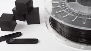
What materials are used for SLS?
The most commonly used material for SLS 3D printing is Polyamide 12 (PA 12), also known as Nylon 12. This material is favored for its excellent balance of mechanical properties, cost-effectiveness, and ease of use.
Other materials, including Polyamide 11 (PA 11) and PEEK, are available, though these are less frequently used due to higher costs and more specialized applications.
Additives such as carbon fibers, glass fibers, and aluminum can be mixed into the polyamide powders to enhance specific properties like stiffness, thermal behavior, or wear resistance. However, materials filled with these additives tend to be more brittle and exhibit anisotropic mechanical properties, meaning their strength and flexibility vary depending on the direction of the print layers.
| Material | Characteristics |
|---|---|
| Polyamide 12 (PA 12) | + Good mechanical properties + Good chemical resistance - Matte, rough surface |
| Polyamide 11 (PA 11) | + Fully isotropic behavior + High elasticity |
| Aluminium-filled nylon (Alumide) | + Metallic appearance + High stiffness |
| Glass-filled nylon (PA-GF) | + High stiffness + High wear & temperature resistance - Anisotropic behavior |
| Carbon-fiber filled nylon (PA-FR) | + Excellent stiffness + High weight-strength ratio - Highly anisotropic |
The SLS 3D printing workflow: From CAD to finished part
Transforming a digital concept into a functional SLS component follows a precise five-stage journey. It begins with Design, where the CAD model is optimized for the powder bed, specifically by adding escape holes to hollow features to allow unsintered powder to drain. Once the file is ready, the print phase takes over, using an automated laser to selectively sinter the material layer-by-layer.
After the build, the part enters a critical cooling stage. A controlled temperature ramp-down is essential to prevent thermal shock and warping. Once stabilized, the process moves to Extraction (Sifting), where technicians ‘dig’ the parts out of the solid powder cake and reclaim the unused material for future builds.
Finally, the parts undergo post-processing, starting with media blasting, to remove any remaining powder, followed by optional aesthetic or functional finishes like dyeing, painting, or vapor smoothing.
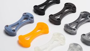
What are the options for SLS post-processing?
SLS 3D printed parts typically have a grainy, powdery surface that can be prone to staining. To enhance the appearance and functionality of these parts, various post-processing techniques can be employed. These methods can significantly improve the surface finish, durability, and aesthetic qualities of your parts:
-
Media polishing: Smoothens and refines the surface texture.
-
Dyeing: Adds color to the part, offering a variety of shades.
-
Spray painting & lacquering: Provides a glossy finish and additional protection.
-
Watertight coating: Seals the part for improved resistance to moisture.
-
Metal plating: Adds a metallic finish, improving strength and conductivity.
For more detailed insights, check out our extensive article on post-processing for SLS parts.
Why choose SLS for production?
One of the greatest advantages of SLS is high throughput. Because no supports are needed, parts can be ‘nested’ in three dimensions. You can stack parts on top of each other throughout the entire build volume, maximizing every cubic inch of the machine.
Limitations: Surface grain and thermal management
While powerful, SLS is not without its drawbacks. The most noticeable is the surface finish, which has a grainy, ‘sugar-like’ texture. If your application requires a smooth or ‘Class A’ finish, post-processing is mandatory.
Additionally, thermal management extends beyond the print time. A full build can require a cooling phase of up to 12 hours before the parts can be safely extracted. If you remove the parts too early, the uneven cooling will cause significant warping, especially on large, flat surfaces.
SLS best practices
Is SLS 3D printing the right choice for your part or project? Here are some rules of thumb to help guide your decision:
-
Material Versatility: SLS can produce functional parts using a wide range of engineering plastics, with Nylon (PA12) being the most common material.
-
Typical Build Volume: Most SLS systems have a standard build volume of 300 x 300 x 300mm, which is suitable for medium-sized parts and small production runs.
-
Mechanical Properties: SLS parts exhibit strong mechanical properties and isotropic behavior, meaning they perform consistently in all directions. For components with special requirements (i.e., enhanced strength or thermal properties), additive-filled PA powders are available, such as carbon-fiber or glass-filled materials.
Get started
Ready to produce durable SLS 3D printed parts for prototyping or low-volume production? Upload your design to get an instant quote, material recommendations, and automated DFM feedback. For project support, contact networksales@protolabs.com.
Frequently asked questions
What are the limitations of SLS 3D printing?
Some limitations include the grainy surface finish of SLS parts, potential for warping on large flat surfaces, and longer lead times compared to other 3D printing methods like FDM or SLA.
What is SLS 3D printing used for?
SLS is commonly used for creating functional prototypes, low-volume production parts, and parts with complex geometries that would be difficult or impossible to produce with traditional methods like injection molding.
Is SLS suitable for rapid prototyping?
Yes, SLS is ideal for rapid prototyping, as it allows for the creation of parts with complex geometries and functional properties, making it suitable for testing prototypes before mass production.