


Sheet metal fabrication
The manufacturing & design guide
Learn how to effectively design sheet metal parts. This guide starts with the basics and moves toward design best practices and advice on material selection, finishings and fastenings, with a focus on two sheet metal fabrication processes: bending and laser cutting.
How does sheet metal fabrication work?
There are several different ways to shape sheet metal, but they all boil down to two broad categories: sheet metal can either be cut or formed.
As there are many different ways of cutting and forming sheet metal, many specific tooling types are needed which can drive up costs. This is why developing a good understanding of the various sheet metal fabrication processes available is essential to producing the most efficient design for a particular application is essential.
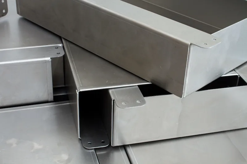
The most basic form of sheet metal fabrication begins with a flat sheet of metal and a blueprint (usually a DXF or CAD file). This blueprint will serve as the instructions on how to cut, form, and finish the base material.
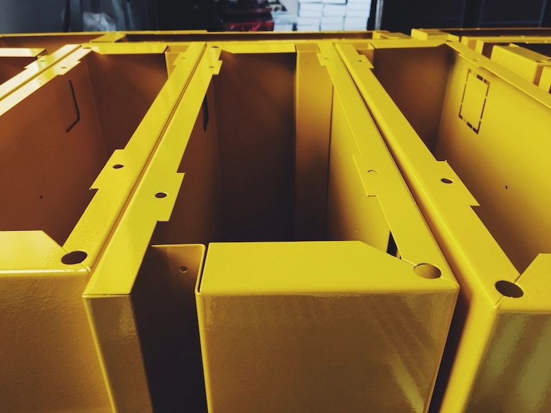
It could be as simple as a single bend to turn it into angle iron, or laser cut and bent at the edges to make computer enclosure panels. When these processes are combined, the material is first cut and later formed, followed by finishing and joining.
What is precision sheet metal fabrication?
Precision sheet metal fabrication refers to some of the exact same methods and techniques as “non-precision” but to a closer degree of tolerance. This will sometimes take the design engineer more time to look at the material properties, stretch calculations, grain direction, and other in-depth research in order to obtain the precision needed.
Benefits and limitations of sheet metal fabrication
As the term sheet metal fabrication covers a wide range of processes and techniques, the advantages and disadvantages very much vary depending on the process. Below is a general snapshot of the benefits and drawbacks of fabricating sheet metal, but to have a more complete understanding of whether a particular sheet metal fabrication process is suitable for your application, more research into each individual process is needed.
Benefits
Fabrication can quickly produce prototype parts with the same precision and speed that it can produce in production. It can also be easily customized, so if the first design doesn’t work as planned - no sweat - the very next part can be adjusted. This customization aspect makes sheet metal versatile, flexible, and affordable when it comes to custom part creation.
When parts approach high volumes, sheet metal becomes even cheaper per-part with exceptionally consistent results.
In this article alone, fourteen types of sheet metal fabrication are mentioned. These varying techniques allow make it possible to create relatively complex parts by cutting flat sheets, bending parts into place and adding holes, slots, and notches cut in all the right places.
Together with the wide range of compatible materials and its ability to withstand (even thrive) in high heat, thermal conduction, electrical, and corrosive environments, sheet metal can be suitable for a diverse number of applications.
Sheet metal can be useful when trying to keep a project lightweight. Adding bends to sheet metal increases the structure’s strength tremendously because it increases the stiffness in multiple axes. Adding a finish to the sheet metal can also make the material resistant to corrosion and scratches.
Limitations
Each technique has limits that make combining different processes a necessity. This can be an advantage, but it can also create longer processing times. For example, a laser cutter cannot make tiny holes, so a drilling or punching process would have to be included.
Some processes, like stamping and roll forming, require custom tooling and equipment to be created to run the process. These custom tools can sometimes be very pricey and only profitable when manufacturing lots of parts.
Some processes require much manual labor, which can drive up the cost per part. Automation can cut down on this labor time cost but is only feasible when high quantities are required.
Bending can be a convenient operation since 3D parts can be created from flat sheets. However, it can also be very complex due to the calculations or trial-and-error aspect of the design cycle. If hole and shaft alignment is necessary, it’s not always straightforward.
Common sheet metal applications
Aerospace
Aerospace engineers used sheet metal for quite a few different lightweight and space ready parts. They create designs for the aircraft or spacecraft out of sheet materials including aluminum and steel, but also use other less common sheet materials like titanium, and tungsten.
The ability to make large, smooth contoured pieces make sheet metal an ideal material for airfoils and other aerodynamic applications.

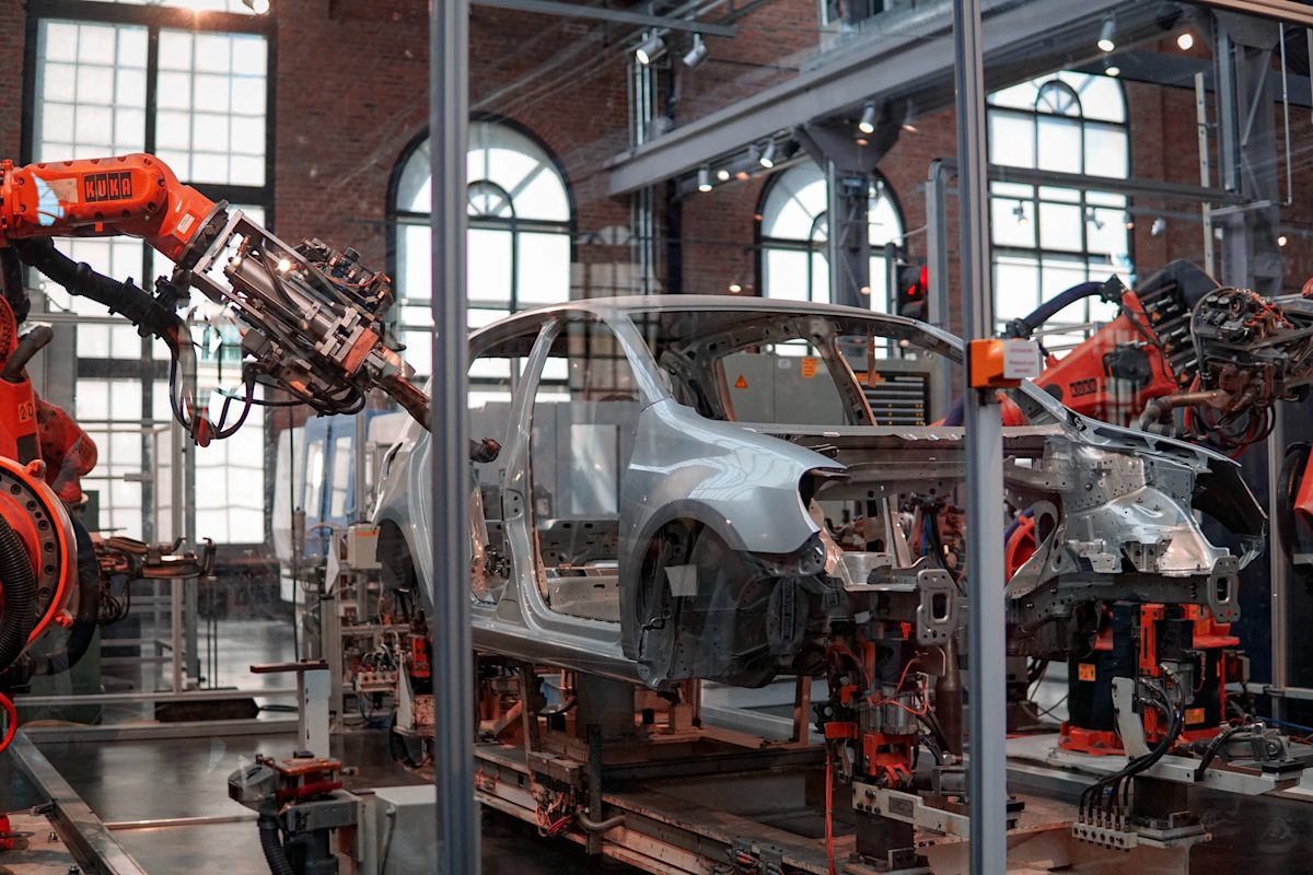
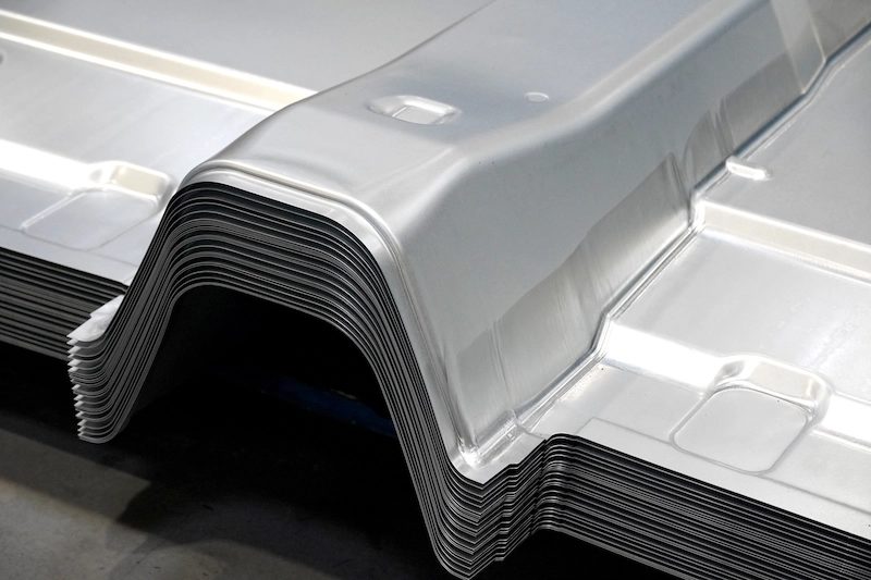
Automotive
Sheet metal has been one of the materials to really kick off the possibility of making automobiles since the beginning. This is due to the large sheet forming capabilities and the ability to make very strong framing out of such thin material. The hood, the fender, the side panels, and the roof are all made from sheet metal that has been cut by laser and punching operations and formed in stamping processes. The frame and exhaust are both roll formed then bent into shape by CNC tube benders. There is a very vast range of automotive components being made that sheet metal fabrication paved the way for.
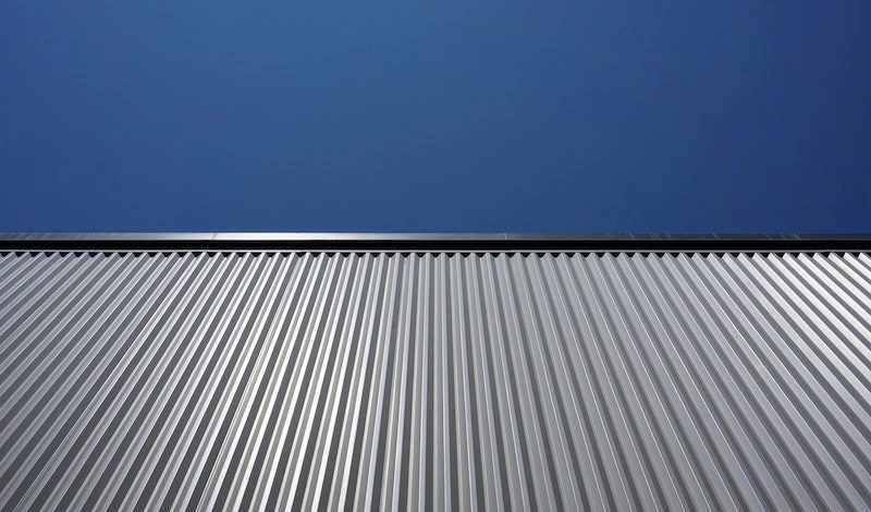
Construction
Metal roofing, corrugated siding, sheet metal 2x4s are all becoming very common and trendy when it comes to construction. Not only does it look good, but it’s also fireproof and tends to reflect heat. This long lasting material can also stand the test of time, so if safety is the top concern, sheet metal construction materials are the go-to substrate.
Healthcare
Healthcare has many unique constraints and demands when it comes to material selection, where sheet metal can be the material to choose in many of these cases. If an MRI is the application, stainless steel and aluminum which are not affected by strong magnetic fields could be the material of choice. High precision tools can be made from sheet metal such as intricate surgery tools and scalpels. An added benefit is some of these materials are chemically inert for the human body and can be easily cleaned and sterilized.

Appliances
Just take a stroll down the appliance section of the nearest hardware store and it is hard not to notice that almost every appliance is enclosed with sheet metal. Stainless appliances with a brushed finish are all the rage recently, where aluminum and powder coated steel have been popular since the dawn of appliances. Although, it is not just the enclosure. Look inside the dryer and see the drum is also completely made of sheet metal, or the refrigeration system has copper capillary tubes that are sheet metal. Sheet metal has made a significant impact on almost all industries.
Part 2
Types of sheet metal fabrication
In this section, we’ll cover and compare fourteen different types of sheet metal fabrication including cutting, forming, stamping, holemaking and threading.
Cutting sheet metal
There are numerous ways of effectively cutting through sheet metal. This section will briefly cover the many different approaches to cut through sheet metal, split into two key groups: cutting with and without shear forces.
Cutting - without shear
Several processes including extreme heat, vaporization, and high pressure abrasive blasting, make it possible to cut through sheet metal without shear. In this section, we’ll cover three main types: laser cutting, plasma cutting and water jet cutting.
Cutting types - without shear
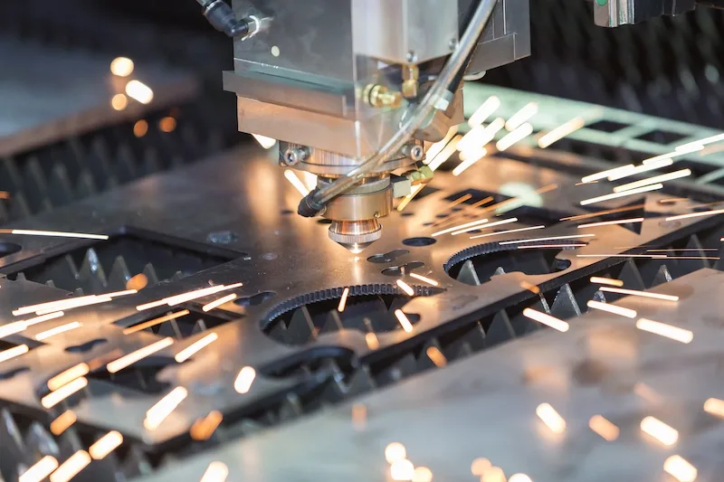
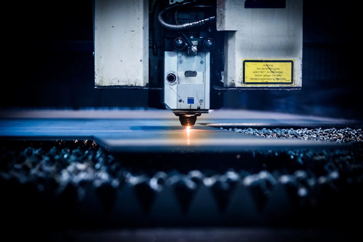
Laser cutting is a process in which a high powered laser beam is focused on a sheet material to heat and vaporize the material away. Most commonly, emitted at a wavelength of 10.6mm (infrared), a CO2 laser is used to pierce through a variety of materials. Efficient, low cost, and productive - these are regularly used in the world of manufacture. A laser resonator creates the laser beam where it is still between 0.5-1.0" (12.7-25.4mm) in diameter. The laser then reflects off several mirrors and focused through a lens to a width of 0.006-0.016" (0.15-0.41mm). A gas laser, typically oxygen or nitrogen, is then introduced into the system right before the laser exits the nozzle.
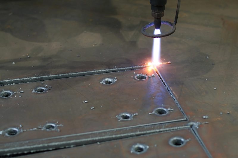
Plasma cutting works in roughly the same way in laser cutting, but is usually used on thicker pieces of metal where the surface finish is not as important. The plasma cutter can only be used on electrically conductive materials and works by creating an electrically charged beam of compressed ionized gas, which is known as the plasma. The plasma is then shot through the cutter into the sheet metal and back to the grounding clamp to form a complete circuit. The material heats substantially and melts away while the compressed gas blows the excess material away. The result is a rough cut that has a large burr and oxidized zone around the cut.
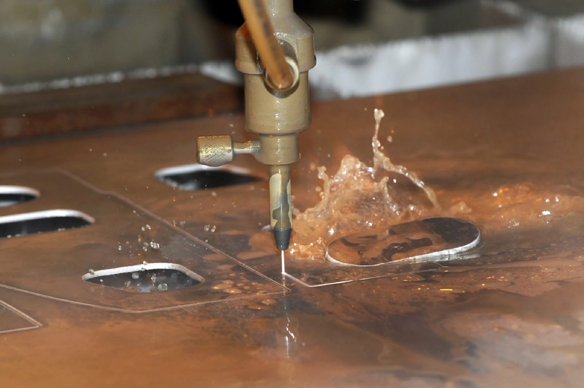
Water jet cutting uses a high pressure and high velocity stream of water containing other abrasives to cut the sheet metal. The velocity of the water stream is typically around 2000ft/s (610m/s) with a pressure of around 60,000 psi (415 MPa). This is basically a high speed version of erosion which typically leads to extremely good surface finishes, no burrs, and since it is being quenched with water the entire time there is no heat distortion. Though if the part is not supported well enough some bending could occur near the cut due to high pressures. Water jet cutting can be a good alternative to laser cutting, but it can be much slower. Also, laser cutting has some extra advantages because it can engrave and part mark using its depth control functionality, where water jet cutting cannot. Water jet also has a larger kerf width of 0.02-0.04” (0.5-1mm) which is much larger than a laser.
Comparison of cutting types without shear
| Types | Pros | Cons | Tolerances | Ideal Mt. range | Cost | Application |
| Laser cutting |
|
|
0.05 mm (0.002 in) | 0.30-1.02 mm (0.12-0.4 in) | $$$ | Medium-thin sheets of material. Becomes less efficient as the material thickness increases. |
| Plasma cutting |
|
|
0.5 mm (0.02 in) | 0.5-180 mm (0.02-7.01 in) | $ | Thicker pieces of electrically conductive metal where aesthetics are not so important. |
| Water jet cutting |
|
|
0.2 mm (0.008 in) | 10.16-50.8 mm (0.4-2 in) | $$$$$ | Parts with intricate details where the finish is worth the extra expense. |
Cutting - with shear
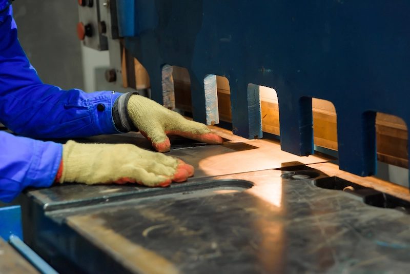
Shearing is a process where the material is cut by a shearing force that overcomes the material’s ultimate shear strength. There is usually a die that holds and supports the material. At the same time, a punch or shear presses down where the die has an opening for the material to be cut through, thus cutting the part. A cut achieved through shearing is different from one that uses another process. The beginning of the cut has a rollover, which leads to plastic deformation of the material from the shear force applied to it. The material then starts to burnish from stretching and rolling against the punch. The shear stress then becomes too much for the material to undergo and the material begins to fracture at a slight angle. There will also be a burr at the bottom of the material due to the material stretching at the beginning of the cut.

Cutting types - with shear
Shearing is typically a process that involves cutting a straight line through the material and separating it into two separate pieces. It is similar to the straight edge paper cutting machine that is in most offices. This process is usually used in order to obtain straight edges on a sheet of metal that has uneven or rough edges. This machinery uses hand power, hydraulics, electricity, or pneumatics depending on the thickness of material and length of the cut needed. The sheet of metal is placed on the die and support arms when the upper blade or punch places a large shearing force onto the material and cuts it. There is a small clearance between the die and the upper blade of about 5-10% of the sheet thickness in order to leave room for plastic deformation and fracture to occur properly. Ideal application: High volume operations. Straight line cuts for softer materials that do not require a clean finish.
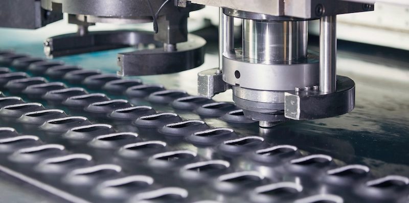
Blanking and punching are essentially the same process with opposing results. Blanking is the process where the sheet metal is held by a die and a punch places a “blanking force” through the material. The material that is punched through is the resulting component where the material still on the die is the remaining blank stock. Punching is the exact opposite where the material that was punched through is scrap and the material still on the die is the resulting component. Ideal application: Medium to high volume operations to create same shaped holes. Finish required to remove burrs.
There are many different types of sawing operations that can be done to cut large pieces of tube or sheet. Whether a band saw or another form of saw that uses a disc saw blade, they work by progressively cutting through the material using a sawtooth tool which makes a series of hundreds of small shear cuts on the material. Each tooth on the saw separates a small chip of material away from the material body through friction and shear forces. Ideal application: Larger workpieces made from softer metals, where tolerance and finish is important. Can produce heavy burrs.
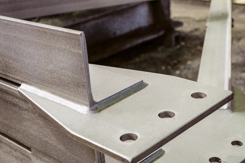
Forming sheet metal
During the fabrication process, the sheet metal is usually first punched and cut in different ways and then followed by forming processes to make a nearly finished and realized product. Entire product chassis can be made in this way. Not only is forming metal convenient, it also adds strength and stiffness to an assembly. In this section, we cover seven different ways to form sheet metal.
Forming types
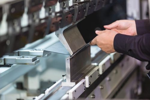
A process where a piece of sheet metal is placed onto a die with a specific geometry and the punch presses into the material to form the sheet metal to the die. Bending sounds easy and straightforward but it can be more complex than expected. For example, if the desired bend is a standard rounded corner, a 45° V-die is used. The material does not reach the inside of the V due to the thickness of the material and instead has a bend radius. Protolabs Network offers sheet metal bending procedures using U-shape dies, V-shaped dies, or channel shape along the straight axis in more ductile materials.
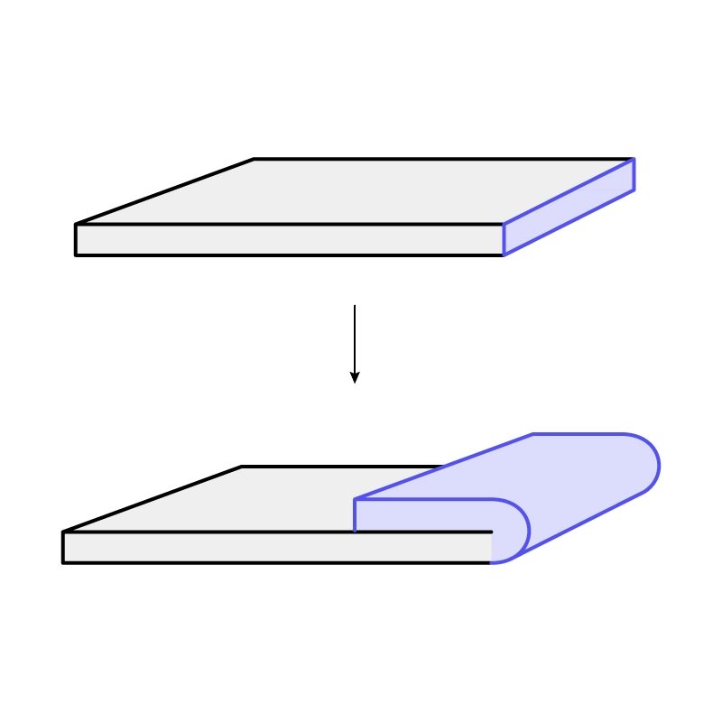
Hemming can be a very useful technique when shearing processes are not available but a nice straightedge without burrs is necessary. Hemming bends the sheet metal upon itself like the hem on pant legs so that the exposed edge is a rounded feature to make the interior of the sheet metal seem like an exterior edge. Hemming is at least a two stage process where a piece of sheet metal is bent and bottomed out into a V-die, then removed and placed into a flattening die to flatten the hem. Hemming is different from a curl because the raw edge is exposed.
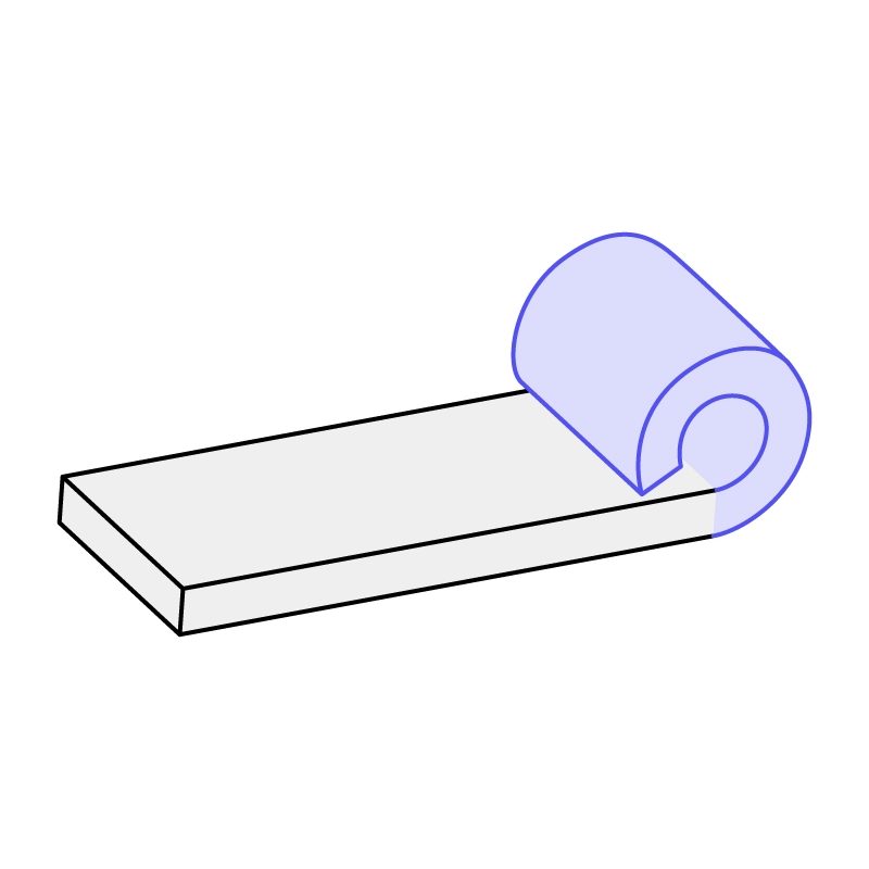
Curling can also be a convenient process for a similar reason to hemming. It creates a nice rounded edge, but with curling the rough edge of the material is completely encapsulated within the curl. It can also be used for hinging applications. Curling usually requires three steps in total where a piece of sheet metal is pressed into a circular die in two locations, then closed together with a circular punch.
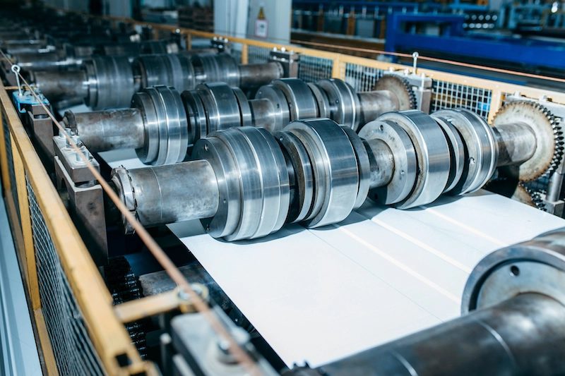
Rolling sheet metal can be a single stage process where a thicker piece of sheet metal goes through as low as 2 (or as high as 20) hydraulically loaded rollers and compresses the sheet metal into a thinner sheet. If it goes through two or more rollers directly perpendicular to the sheet metal, the material is flattened to thinner material. With the usage of more rollers in different geometry and distances from each other the material can be shaped into different shapes.
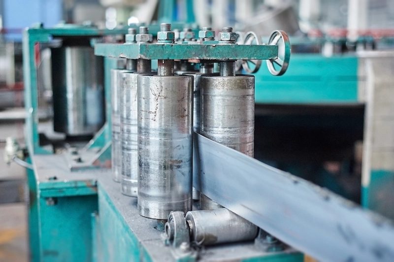
Roll forming can create long sections of complex geometries. Roll forming takes a long piece of sheet metal, usually stock comes from a spool, and goes through a series of roll dies that gradually bend the sheet stock into a progressively more intricate shape. This process leads to different types of tubing such as square and cylindrical tubing, or different types of channeling such as U-channel or other complex shapes.
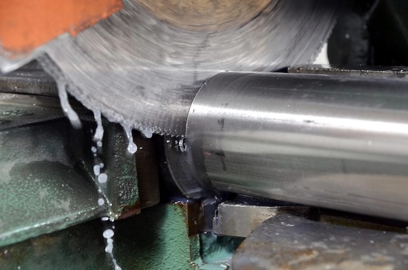
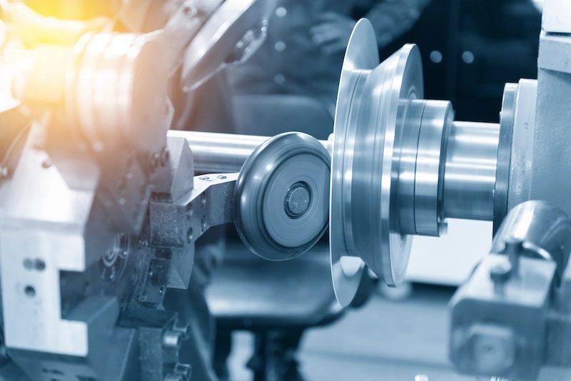
Metal spinning consists of a disk or cylinder of sheet metal that is placed onto a mandrel on a lathe and a roller tool shapes the sheet to the mandrel shape.
- Conventional spinning: constant wall thickness, but finished part will have a small diameter than the blank
- Shear spinning: constant outer diameter between blank and finished part, but wall thickness will be thinner.
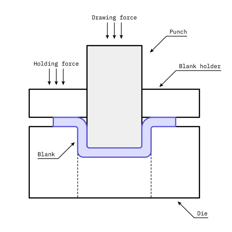
Deep drawing machinery is similar to that of the shear punch but this time there is more clearance between punch and die which creates the final wall thickness of the drawn section. The punch will also have a radius as opposed to a sharp edge to avoid marring the sheet metal. The part is held by a die and the punch draws into the sheet metal to stretch and form the material between the punch and die.
Stamping sheet metal
Stamping can be a complex combination of cutting and forming using the previous techniques of shearing, bending, stretching, and even joining using intricate dies to obtain a complex part in a shorter amount of operations. Sometimes the process can be a progressive stamping process where there are multiple stamping stations that gradually cut or form the part further and further until the final piece is created.
Holemaking and threading
Making holes in sheet metal can be done with some of the previously mentioned processes including laser cutting and punching, but there are also other ways that will be mentioned here. A CNC mill, drill press, or hand drill may be utilized in order to make holes in material. A CNC machine will be the most precise out of these options, the hand drill will usually be the least precise.

Part 3
Design for sheet metal fabrication
In this section we’ll cover the best practices to follow when designing for sheet metal bending and laser cutting ー the two sheet metal fabrication services we offer. We’ll begin with general considerations when designing a sheet metal parts, and then move on to best design practices for laser cutting, bending, and creating holes.
Sheet metal general design considerations:
Wall thickness
As sheet metal parts are fabricated from one sheet of metal, the part must maintain uniform wall thickness throughout. We recommend a sheet metal thickness range between 0.5-10 mm (0.02-0.394 in) for laser cutting and 0.5-6 mm (0.02-0.236 in) for bending.
Tolerances
Sheet metal fabrication tolerances are often slightly larger compared to CNC machining tolerances, as bends in the material can cause the material to stretch. It’s important to note that the more processes a part undergoes, for instance if a part has multiple bends, the more difficult it becomes to achieve tight tolerances. We offer the tolerances displayed on the right, which are generally acceptable in the industry. Although higher tolerances are achievable, extremely high tolerances can make a process more difficult and significantly drive up costs.

Design best practices for laser cutting:
Add fillets to the corners to create a smooth finish
The corners of sheet metal parts can be extremely sharp, so it’s recommended to add fillets, half the size of the material thickness, into your sheet metal design to avoid cuts from handling the part.
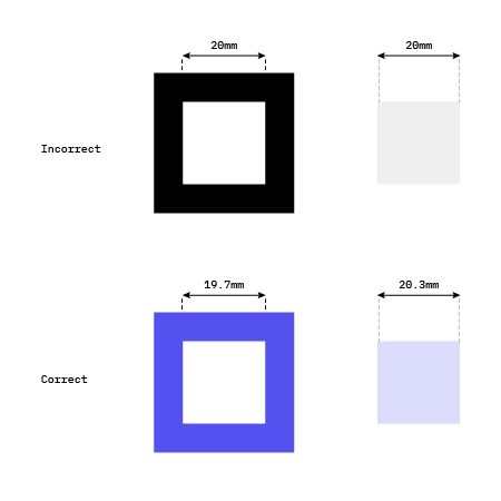
Consider the kerf
A small amount of material is removed during the laser cutting process, which is called a cutting kerf. Compared to waterjet cutting or plasma cutting, laser cutting produces the lowest kerf at 0.3 mm on average, but the exact amount is dependent on the material and laser beam width. This is particularly important to remember if parts you are designing need to fit into one another when assembled. The rule of thumb is to add half of the kerf to the inner object and subtract the other half of the kerf from the outer part.
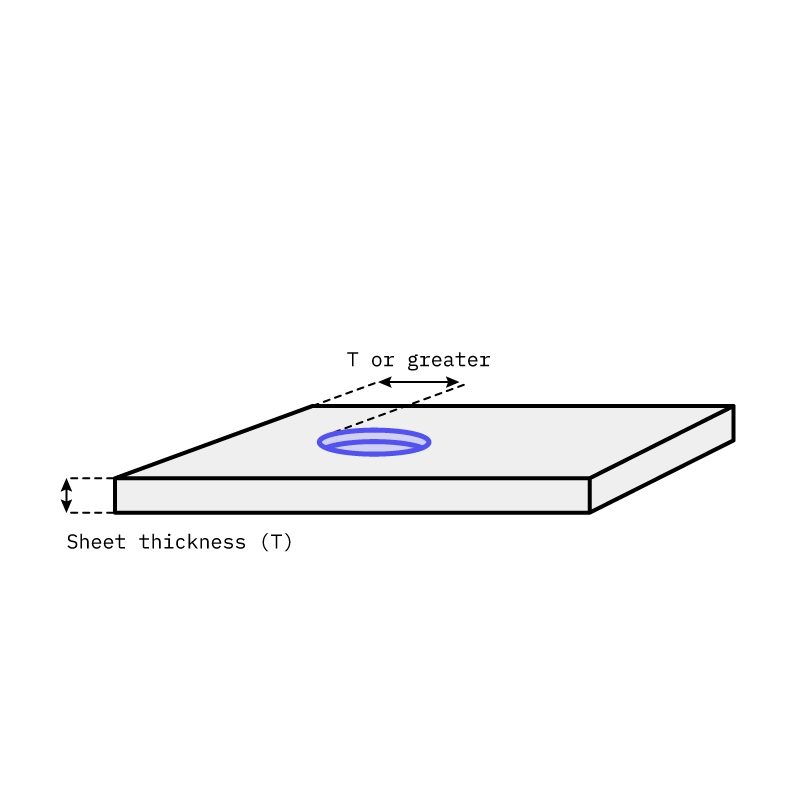
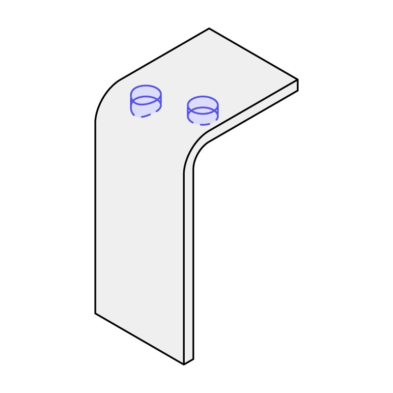
Specify hole diameters larger than the sheet thickness
Holes with a diameter less than the thickness can lead to deformation or may be inaccurate due to the kerf or distortion caused by the laser beam. It is possible to laser cut holes with a diameter smaller than the material thickness, but if you want to stay on the safe side stick to a diameter the same size or greater that the sheet thickness.

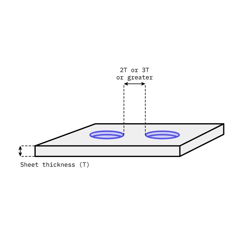
Space holes at least 2 times the sheet thickness apart
Holes that are too close to each other can lead to deformation or breakage during forming or bending.
Holes should be at least the sheet’s thickness from the edge
If holes are placed too close to the edge, the possibility of the hole tearing or deforming is higher, especially if the part later undergoes forming.
Ensure holes are at least 2 times the sheet thickness from the start of the bend radius
If the hole is placed to close to the bend, the hole may become distorted or may act as an unintended relief cut.
Design best practices for bending:
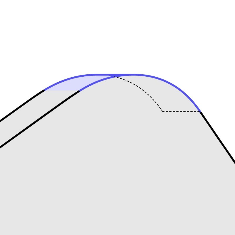
Consider K-factor to avoid deformation and tearing
When bending metal, the material stretches, which consequently shifts the neutral axis away from the center. In order to design a flat pattern correctly and find the right bend allowance, you can find the neutral axis along the bend by calculating the K-factor. K-factor is a constant that shows the ratio of the neutral axis to the material thickness: K-factor = t/Mt

K-factor changes based on material, thickness, bend radius, bending method (i.e. air bending vs bottom bending vs coining). Because of all these specific variables it’s hard to calculate K-factor completely accurately, but it should range between 0.3-0.5 mm and the average is 0.4468 mm which is used for most bending applications. As a guideline, you can use the values in the chart below:
| Generic K-factors | Soft materials (e.g. aluminum) | Medium materials (e.g. steel) | Hard materials (e.g. stainless steel) |
|---|---|---|---|
| Air bending | |||
| 0 - Mt. | 0.33 | 0.38 | 0.40 |
| Mt. - 3x Mt. | 0.40 | 0.43 | 0.45 |
| > 3x Mt. | 0.50 | 0.50 | 0.50 |
| Bottoming | |||
| 0 - Mt. | 0.42 | 0.44 | 0.46 |
| Mt. - 3x Mt. | 0.46 | 0.47 | 0.48 |
| > 3x Mt. | 0.50 | 0.50 | 0.50 |
| Coining | |||
| 0 - Mt. | 0.38 | 0.41 | 0.44 |
| Mt. - 3x Mt. | 0.44 | 0.46 | 0.47 |
| > 3x Mt. | 0.50 | 0.50 | 0.50 |
If you want to use a more exact K-factor, rather than use this chart, you’ll need around 3-5 test pieces to gather some information, including bend allowance (BA), bend radius (Ir) and material thickness (Mt). More detailed information on calculating the K-factor can be found in this article.
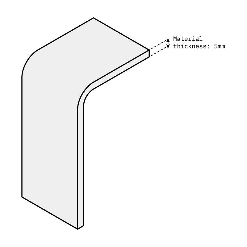
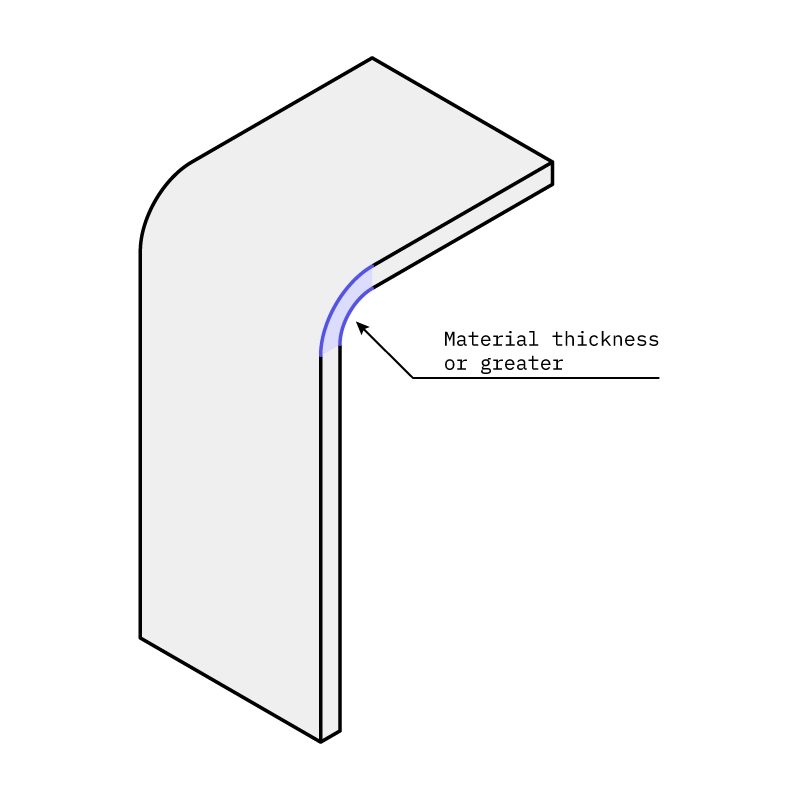
Keep the interior bend radii at least as large as the material thickness
When bending sheet metal, it’s impossible to create a completely sharp corner. There will always be a slight curve which is called a bend radius. In order to avoid distortion around the bend, parts should be designed with the interior bend radius to be the same size or greater than the material thickness.
Use the same radii with consistent bend orientations to reduce costs
Inconsistent bend orientations and varying bend radii mean the part will be need to be reoriented more often, which requires more time from the machinist. Keeping the radii and bend orientation consistent will reduce the amount of part reorientations, and consequently save time and costs.

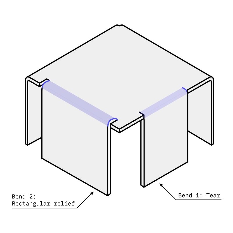
Add bend reliefs to prevent tearing and reduce springback
When there’s material on either side of the bend, stress can build up in these areas, causing the material to deform or tear. Relief cuts or bend reliefs can relieve this stress, as well as adding stiffness and reducing the amount the sheet metal naturally springs back once bent. To add a relief cut to your design, add an incision either side of the bend that is at least the same width or greater than the material thickness.
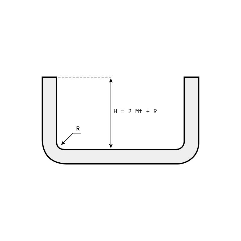
Ensure the bend height is at least double the material thickness plus the bend radius
Small bend heights are more difficult to form and position in the press brake, which can result in deformation.
Part 4
Materials & finishes
One of the key advantages of sheet metal fabrication is the wide selection of materials and finishing available. This section first offers guidance on how to choose the right material for sheet metal fabrication and the factors to consider, and then covers the available surface finishes and their most suitable applications.
Sheet metal materials
The mechanical properties of materials used for sheet metal fabrication are the same as the base metal, so your decision of material should be largely based on choosing an appropriate material according to your needs. However, the materials most suitable for sheet metal fabrication are those which you can manipulate and do not lose their physical properties. Aluminum and steel are examples of such materials. Additionally, as sheet metal fabrication projects often include bending, machining or welding, there are a number of factors to pay particular attention to when selecting an appropriate material. These include:
- Ductility (elongation at break)
- Machinability
- Weldability
- Tensile strength
- Corrosion resistance
- Weight
- Cost

Common materials used for sheet metal fabrication
This section compares the properties of different grades of the standard sheet metal fabrication materials offered by Protolabs Network, including aluminum, stainless steel, mild steel, and copper. More general descriptions of these metals can be found on this materials page.
| Material + grade | Elongation at break | Machinability | Weldability | Corrosion res | Tensile strength | Cost |
|---|---|---|---|---|---|---|
| Aluminum 5052* | 7 - 27 % | Fair | Good | Excellent | 195 – 290 MPa | $ |
| Aluminum 5754* | 10 - 15 % | Good | Excellent | Excellent | 160 - 200 MPa | $ |
| Stainless Steel 304 | 45 - 60 % | Excellent | Excellent | Good | 480 - 620 MPa | $$$ |
| Stainless Steel 316L | 30 - 50 % | Good | Excellent | Excellent | 480 - 620 MPa | $$$$ |
| Mild Steel 1018 | 17 - 27 % | Good | Excellent | Poor | 190 - 440 MPa | $$ |
| Copper 110 | 15 - 50 % | Poor | Moderate to Poor | Good | 220 - 230 MPa | $$ |
Sheet metal finishes
The finishing of sheet metal can be one of the most crucial steps in ensuring that the product not only works, but works for as long as possible. Leaving some types of metal unfinished can lead to devastating corrosion or electricity going where it shouldn’t. The types of finishes available for sheet metal are no different from those used for other metal fabrication processes. How suitable a finish is depends heavily on the part’s individual requirements and the properties of the selected material. The most common finishes and how they applicable to sheet metal are compared below. For more general descriptions, information on roughness, color options, grit etc., and images of each of these finishes, check out this page on surface finishes.
Comparison of sheet metal finishes
| Finish | Description | Pros | Cons | Rough price increase | Application |
| Bead blasting | Shooting glass beads or other abrasives at the part at high speed, resulting in a uniform matte or satin surface finish. |
|
|
+5% | Used mainly for visual purposes and to prepare surfaces for other coatings. Comes in several different grits which indicate the size of the bombarding pellets. Can be combined with anodizing. |
| Powder coating | Powder coating adds a thin layer of protective polymer on the surface of the part. |
|
|
+15% | All metals. Both decorative and protective and can be combined with bead blasting. |
| Anodizing | This is an electrochemical process of placing a stable oxide coating on the material, usually aluminum. |
|
|
+20% | Can be used on aluminum, titanium, zinc & magnesium to increase corrosion resistance and visual appeal. |
| Chromate conversion coating | Known also as alodine or chemical film, this process immerses parts in a chemical bath until a coating has formed. |
|
|
+10% | Best for functional parts, not intended for decorative use. |
| Brushing | Brushing is produced by polishing the metal with grit resulting in a unidirectional satin finish. |
|
|
+5% | Brushing is mostly used for aesthetic purposes and can be used to cover up imperfections from machining for customer-facing parts. |
| Brushing + electropolishing | Parts are brushed and then run through an electropolishing process - an electrochemical process used to polish, passivate and deburr metal parts. |
|
|
+15% | Best for parts that need to be smooth at a microscopic level. Suitable for the majority metals, but mostly used for stainless steels. |
Part 5
Joining sheet metal parts
Once created, there are various approaches to joining sheet metal parts suited to different applications. This section quickly summarizes these approaches, including fastenings, welding, and soldering, and describes their advantages and disadvantages. There are also additional methods for joining sheet metal that don’t require fasteners like crimps, notches and tabs which rely more heavily on the part design, that are not mentioned in this list but may be relevant to explore.
Fasteners
Fasteners are hardware devices that mechanically join or affix two or more objects together. They are used to create non-permanent joints, as opposed to welding. The most common type of fasteners for sheet metal are called PEM fasteners. PEM is a brand that creates fasteners to provide threaded inserts and mounting points for sheet metal and PC boards.
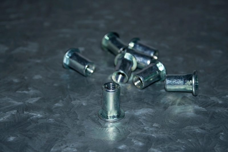
There are several different categories of fasteners, including nuts, cable tie-mounts and hooks, inserts, studs and pins, standoffs, captive panel screws and hardware, weld nuts, and sheet-to-sheet attachments. All of these categories serve a slightly different purpose and there are multiple hardware options within the categories. Explore the specific types of fasteners available in this overview →
Welding
When joining and fastening sheet metal, one of the go-to techniques is definitely welding, which involves fusing parts together at high temperatures. MIG welding and TIG welding are ideal when dealing with sheet metal, although other processes also work. Welding tends to warp and create heat zones that can be non-ideal for a finished product, but MIG and TIG welding help lessen these challenges.
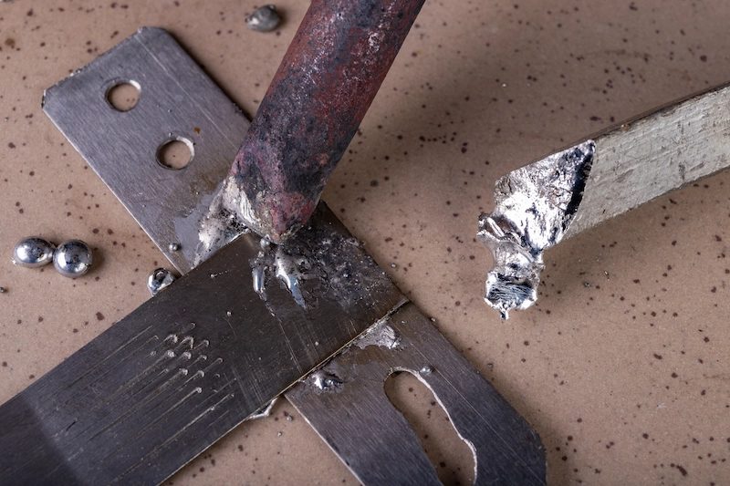
Soldering
This process differs to welding because the base metal doesn’t metal in the process. Instead, a filler metal is heated until molden and used to join two parts. Soldering copper tubes is a very common plumbing technique where the strength of a brazed joint is not necessary. Solder joints are usually not as strong due to the ductile nature of most solders and the melting point which is usually less than 450°C.
Part 6
Additional resources
In this guide we touched on everything you need to get started with sheet metal fabrication - but there’s plenty more to learn. Good sheet metal design goes beyond basic guidelines and considers the type of sheet metal fabrication process, material, finish, fastening, and tailors all these factors to the specific function. Here are some useful resources on sheet metal fabrication, as well as other resources related manufacturing if you want to delve deeper.