Introduction
This is a continuation of the previous tutorials on 3D modeling an enclosure. In the previous two articles a two-part housing was created followed by the addition of a living hinge. Follow the 3D modeling enclosures guide, & 3D modeling a living hinge guide, or download the Fusion 360 enclosure file to follow along from here.
This guide demonstrates 3D modeling techniques for creating functional snap-fit joints. Fusion 360 has been used to model these parts but most CAD packages are very similar in operation. If you don’t currently have Fusion you can download a free copy for hobbyist use here.
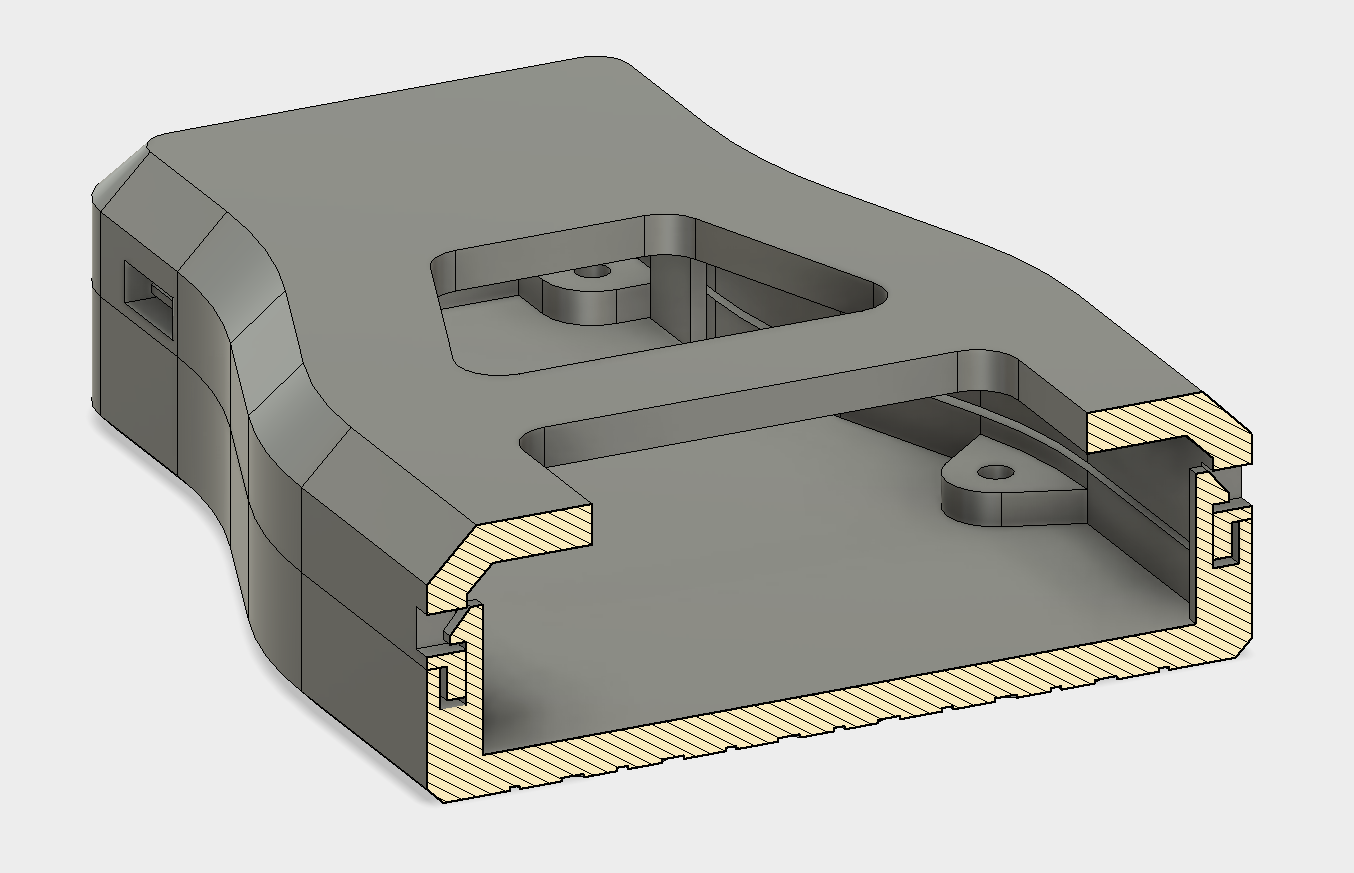 Section view of the completed snap fit features.
Part 1 - Snap-fit Cut-out
We will be using a cantilever snap-fit joint for this part. The cantilever is the most common snap-fit joint and consists of a protrusion (some type of bead or hook) at one end of the beam and a structural support (usually a cut-out) at the other end. This protrusion is inserted into a cut-out or slot and deflects upon insertion. Once fully inserted the hook bends back locking the connection into place.
Using snap fits with 3D printed parts is useful as it allows pieces to be assembled easily without the need for other components such as fasteners or glue. To learn more about design requirements for snap-fit joints check out this article.
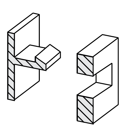 Diagram of 2 part snap-fit joint.
The most effective method of creating the snap-fit feature is to start with the slot cut-out. This is then used to reference the hook which will be modeled later. For this design a simple rectangle extrusion is used which the hook will latch into. Only one snap-fit joint needs to be created as it can then be Patterned around the edge of the case, saving time and making it easier to modify if the design changes.
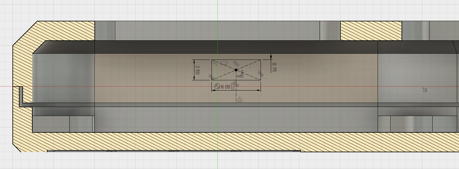
The first sketch was created on the inside face of the bottom section of the enclosure as shown in the screenshot. A simple rectangle is used, with dimensions of 2.5x6mm, and offset from the top wall by 0.75mm.
Note: It becomes hard to see the geometry when sketching on an interior face as the other wall blocks the view. To make it easier to construct this sketch you can use the Slice option in the sketch palette to create a temporary section view of the part.
 Location of sketch on the inside enclosure assembly.
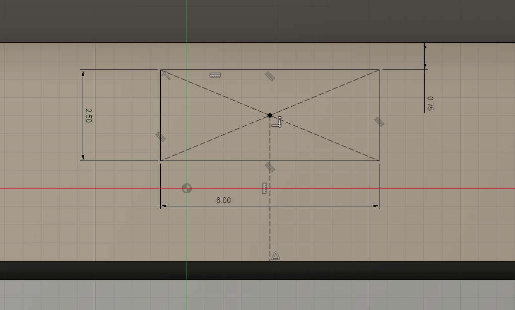 Sketch geometry for the cut-out.
This profile is then Extruded Cut to create the slot for the hook to fit into. For this design the slot is cut through the case. This was done to allow easy disassembly when testing components. The cut-outs can also be blind (only partially cutting into the wall) resulting in a cleaner design as the cut-out is not visible from the outside.
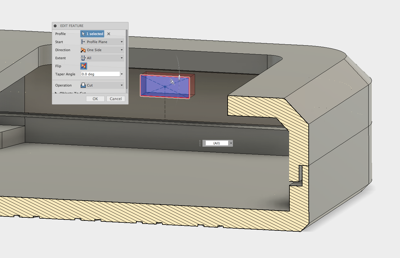 Extrude cut of the cut-out profile.
Part 2 - Clip Hook
The next stage is to create the clip. It is possible to reference the cut-out in the previous step to ensure the hook and cavity line up perfectly. A Midplane construction plane is used which enables a sketch to be created in the center of the cut-out.
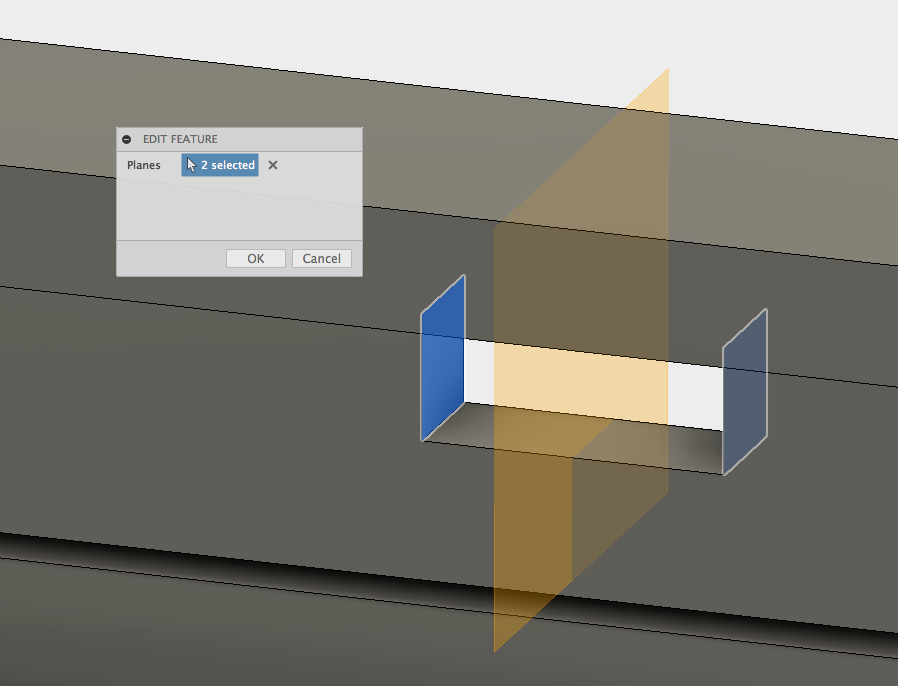 Midplane construction plane.
The sketch for the hook can now be created on this workplane. Again the Slice option was used to show this section of the design while sketching.
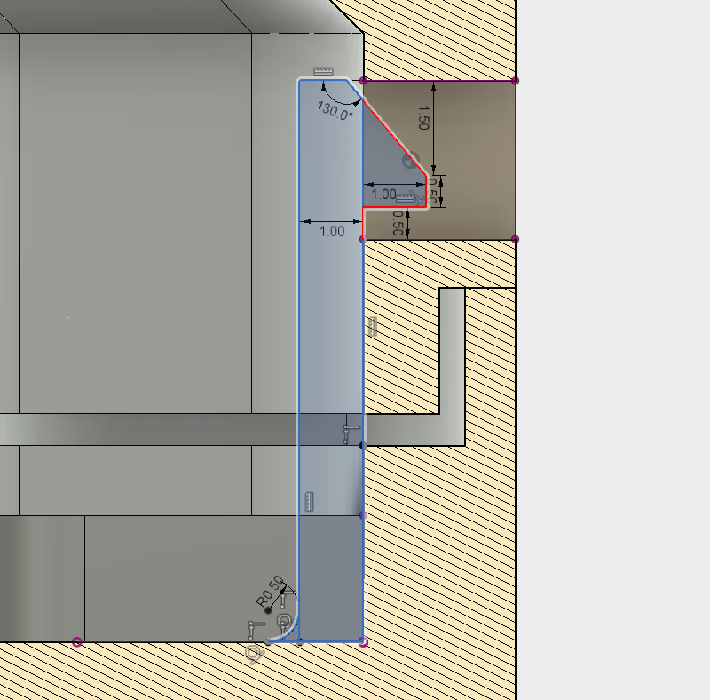 Sketch with hook profile highlighted.
It is important to leave a small clearance to account for inaccuracies during printing. For this design, 0.5mm was selected and is a good starting point for most 3D printing clearances. Multiple geometry variations and dimension values were tested to develop an optimal hook design that was reliable. The dimensions for this hook can be seen in the screenshot. A fillet was also added to the base of the clip to improve the deflection strength when the case is being assembled.
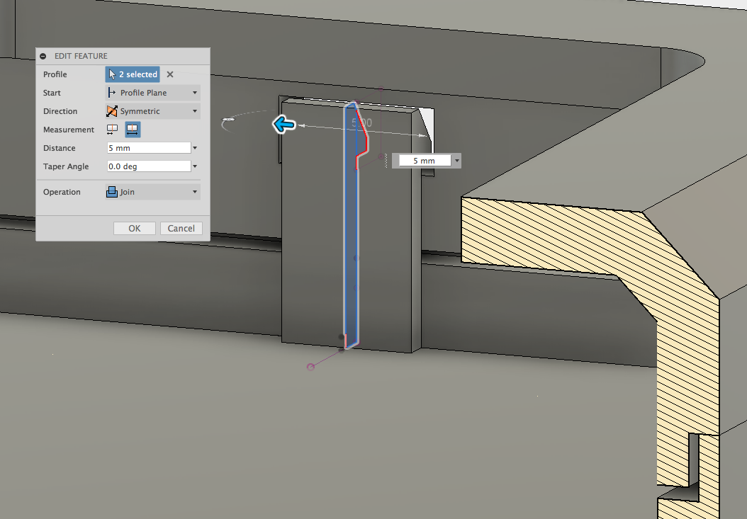 Hook profile being extruded.
The hook profile can now be Extruded to a distance of 5mm. Increasing this width will add strength to the design (if this is feasible in the design constraints). This may require trial and error to achieve the correct stiffness however it is recommended the clip should be at least 5mm wide.
The sketch is located in the middle of the cavity so a Symmetric Extrusion was used. The bottom section of the enclosure was hidden to ensure it did not join to the top part when extruded.
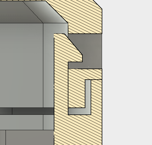 Section view of the completed snap-fit feature.
Part 3 - Pattern Features
The single snap fit joint is now complete, however more joints are needed for this part to be secure around the entire perimeter. The Pattern command can be used to efficiently create multiple copies of the snap-fit joint, without the need to create any new sketches or extrusions. Using the Pattern tool also means that it is much easier to adjust the position or quantity of the snap-fits later in the design.
The final stage is to pattern the snap-fit feature around the inside of the part. The Pattern on Path tool is used to create multiple iterations of the single hook and cavity.
The Pattern Type is set to Features and then the previous Features created before are selected (the slot and cantilever) from the history browser at the bottom of the Fusion workspace. The path that the parts should follow is then selected and the quantity of instances are defined.
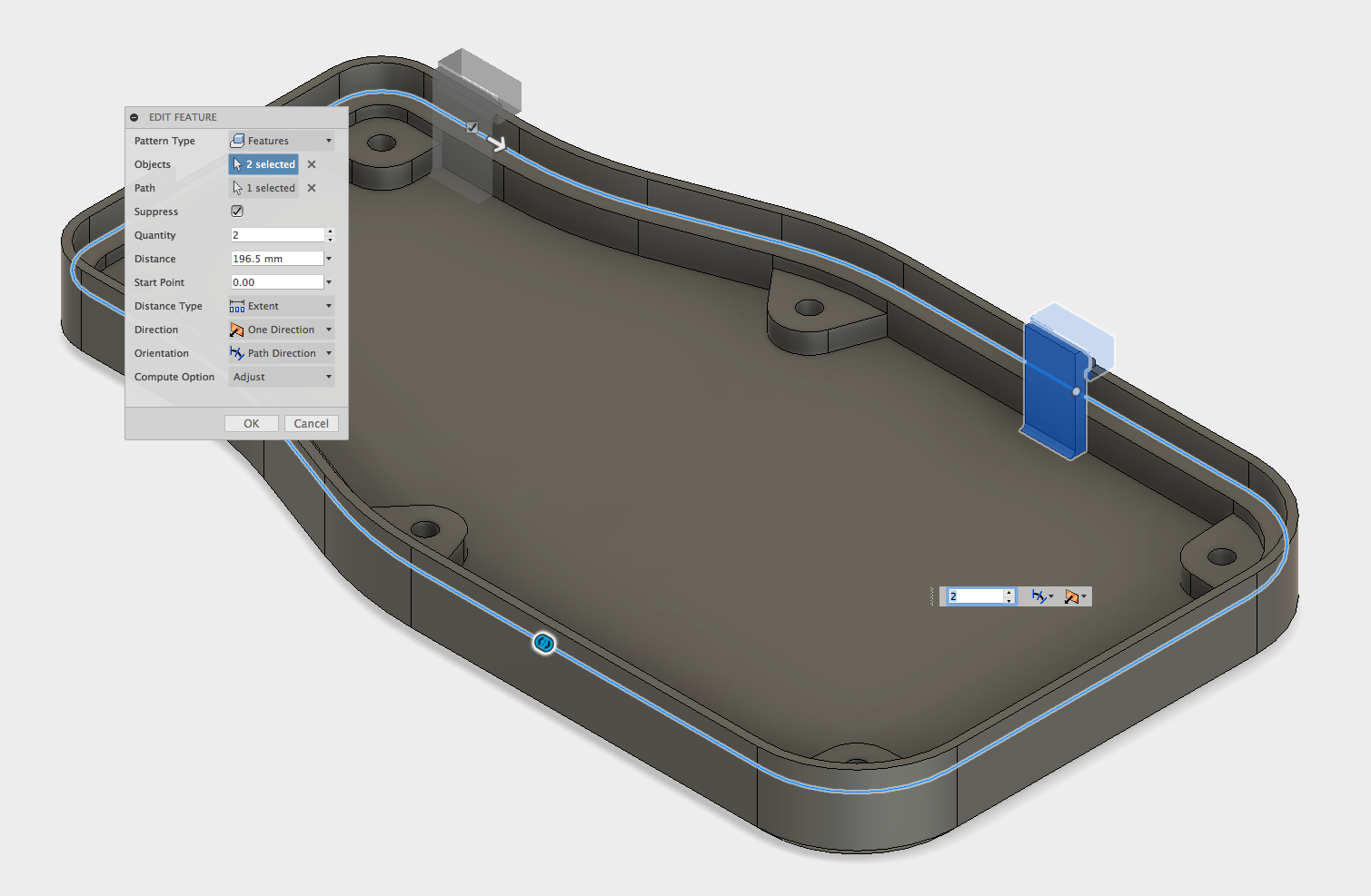 Pattern on Path tool used to duplicate the snap-fit.
The top part was temporarily hidden so the path could be selected for the new clips to follow. Specifying a different Quantity and Distance change the position of the snap fit features, so they don’t intersect with other parts, such as the mounting bosses. It is also important to set the Orientation to Path Direction so all of the clips are perpendicular to the face they are on.
For this part a combination of the Pattern on Path & Mirror tool is used. First the Pattern is created and then the Mirror tool is used to reflect the joints to the other side, resulting in a perfectly symmetrical design.
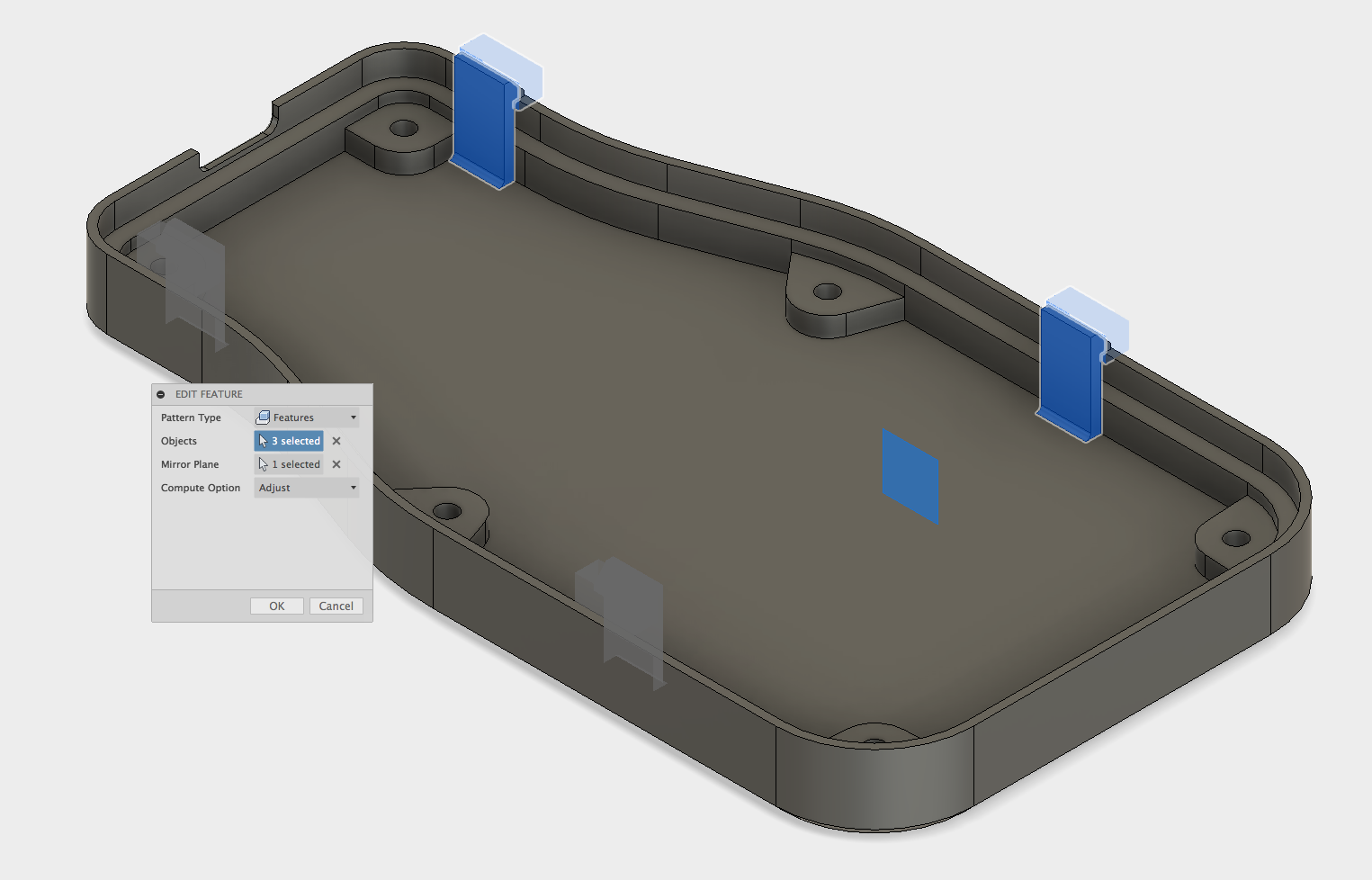 Mirror tool reflecting the snap-fits.
 Completed snap-fit joints.
The snap-fit features are now complete, comprising of four separate snap-fit hooks and cavities that secure the top & bottom case halves of the enclosure. If you would like to take a more in depth look at this model you can download the Fusion 360 file and also the STL files.
Note: The part is designed to be printed flat as shown in the screenshots, as this will result in a nice outer surface finish and a strong snap fit joint. Support material was not used on this part as the overhangs are very small, and the cleanup of the support would have been difficult.
Learn more from our in-depth 3D printing guide here.