


Introduction
This guide demonstrates 3D modeling techniques for creating functional enclosures. Fusion 360 has been used to model these parts however most CAD packages are very similar in operation. A free version of Fusion can be downloaded here.
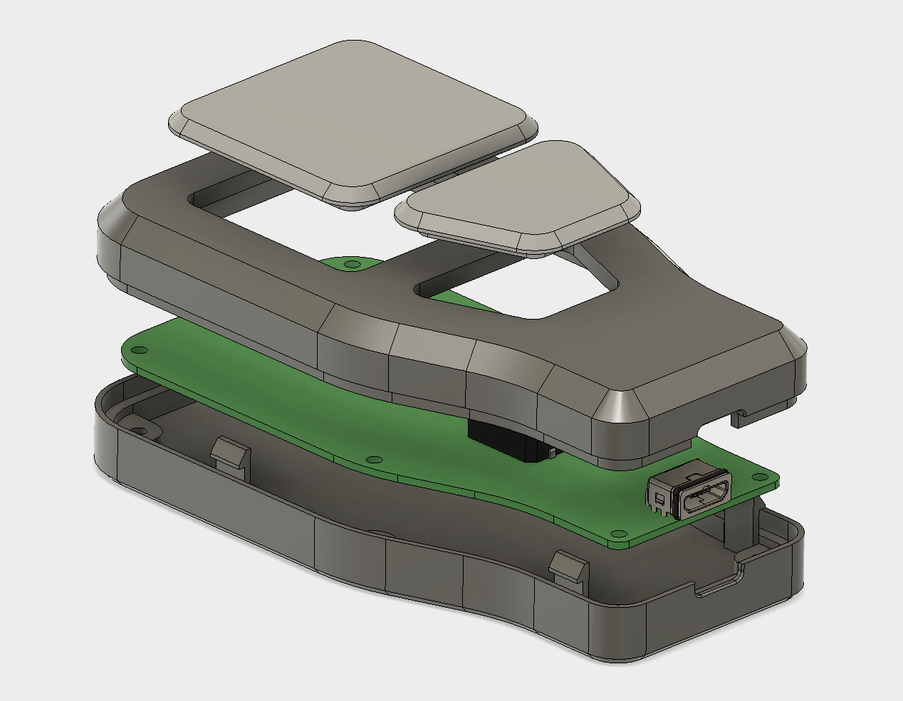 Exploded view of case assembly.
This guide will look at designing an enclosure for a small remote control. It is a 2 part design that has a opening on the end for a micro USB connector and houses two push button switches. The part will be printed using FDM (Fused Deposition Modeling). Other printing technologies can also be used such as SLA, SLS and material jetting, however FDM is great for prototyping cost effective enclosure designs.
The first stage is to model the main body of both the top and bottom of the enclosure, modeling both of the Bodies solid and then creating the cavity required for the circuit board using the Shell command. The opening for the micro USB connector and the mounting bosses for the circuit board will then be added.
Part 1 - Base Features
The first sketch will allow us to generate the main body of the enclosure. The sketch is created on the Top Plane of the origin. This sketch would generally reference the dimensions of an existing circuit board and components, however it is possible to design the case first, and then design the electronics layout. The sketch only includes Lines and Center Rectangles at this stage, Fillets will be added later. The sketch is fully constrained to the origin which is good practice as it will make it much easier to reference other features later in the design.
Note: The buttons were also added to this sketch, which will be used later in the model.
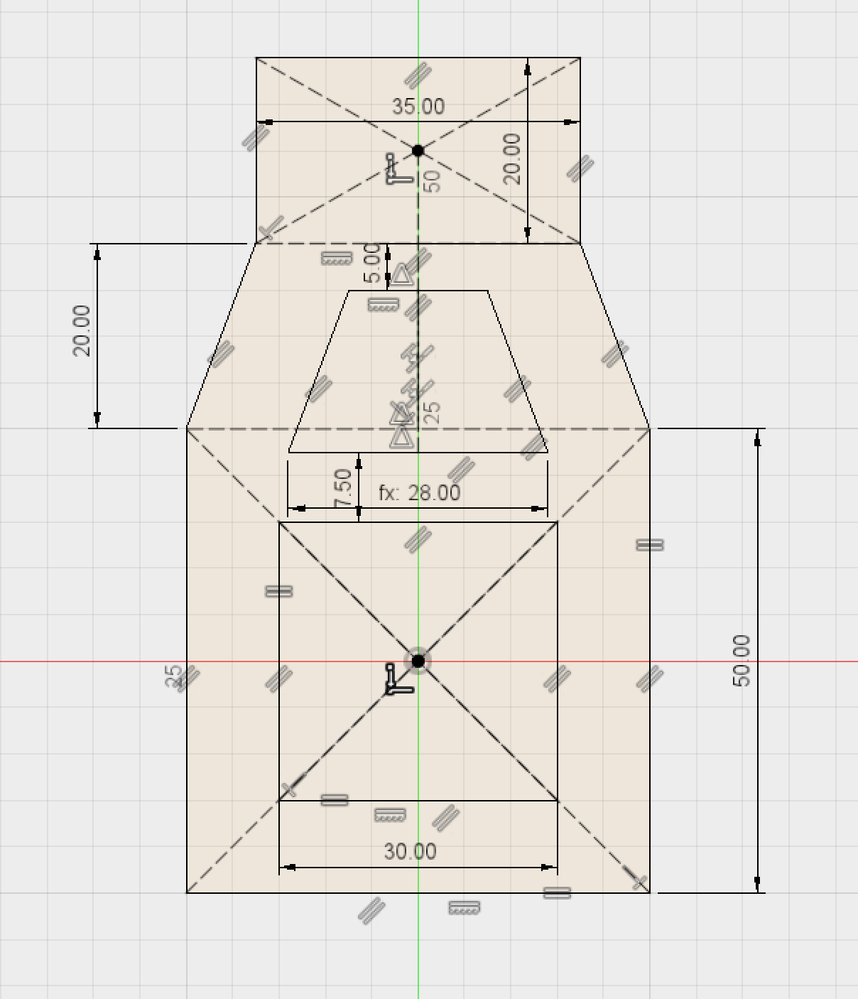 Sketch of the main profile.
The profile of this sketch is then Extruded 8mm to create the first half of our enclosure. This will create a new body that will become the top part of the enclosure design.
 Main body extrude.
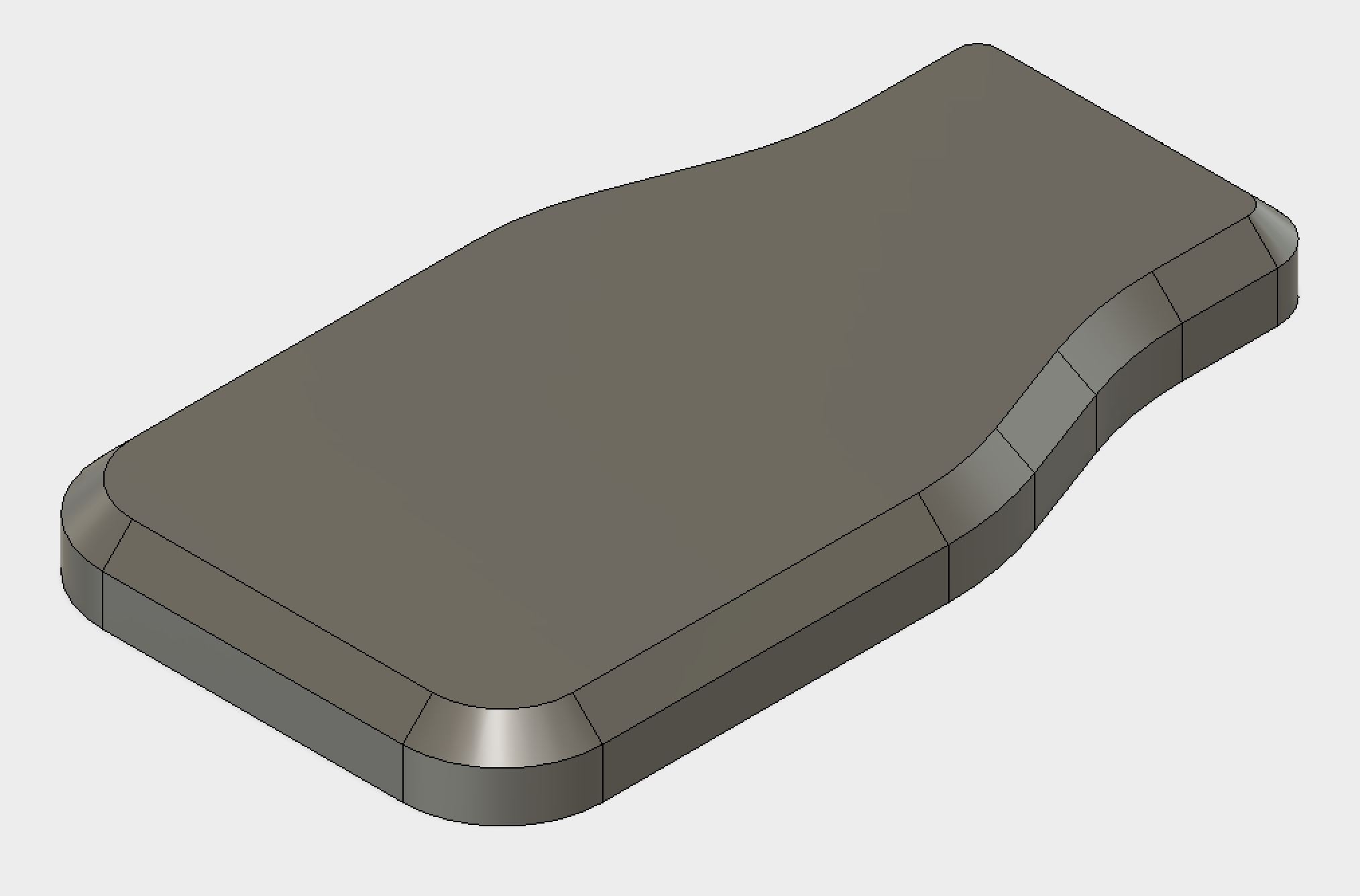
It is now possible to add Fillets (curved edges) and Chamfers (angled edge breaks) to make the case more visually appealing and to improve the printing process. In total, Fillets with 3 different sized radii were used; 10mm on the closest two edges, 30mm for the middle four edges and 5mm on the far edges. In addition a 3mm Chamfer is added to the perimeter of the top edge.
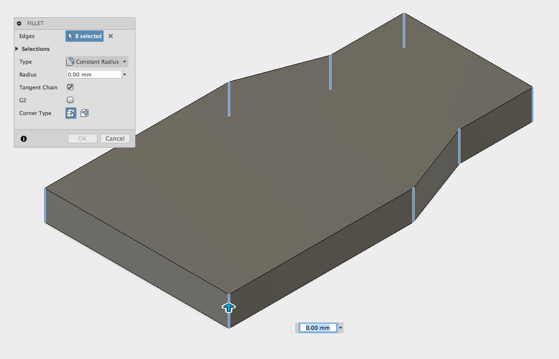 Fillets being added.
Note: For FDM printing it is a good idea to reduce the number of sharp corners as much as possible. The printer has to decelerate and then accelerate when changing direction at the corner, which reduces the speed, increasing print time substantially over many layers.
 Fillets being added.
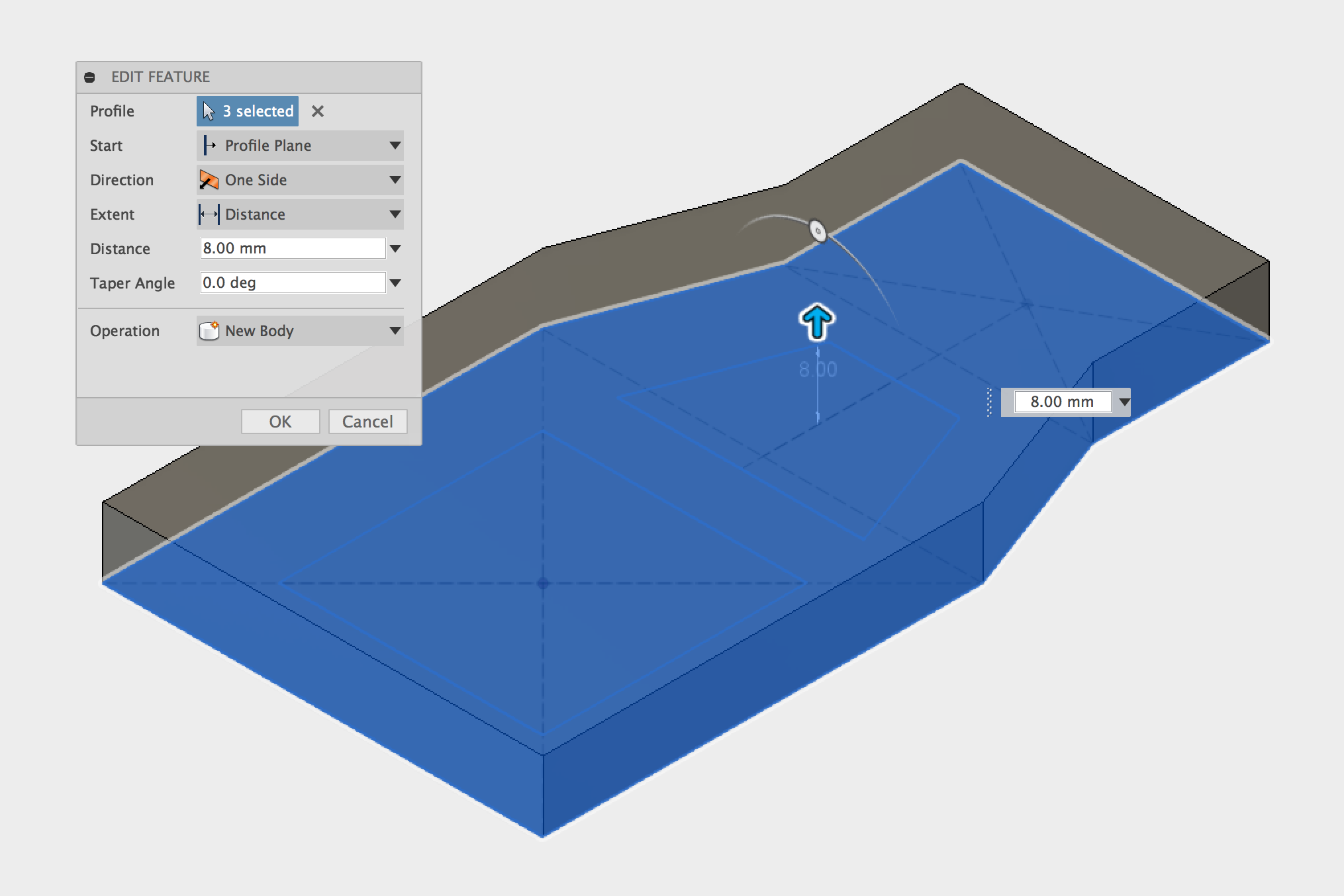
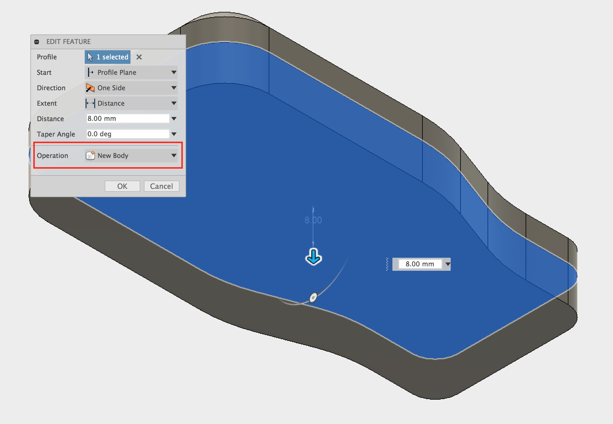
The second part of the enclosure can now be Extruded down by 8mm to create a matching half. It is possible to use the bottom face of the first body for the Profile without creating a new sketch. It is important to select New Body for the operation here as Fusion will choose Join by default which will just add material to the top half of the enclosure.
 Top half of the enclosure with Fillets and Chamfers.
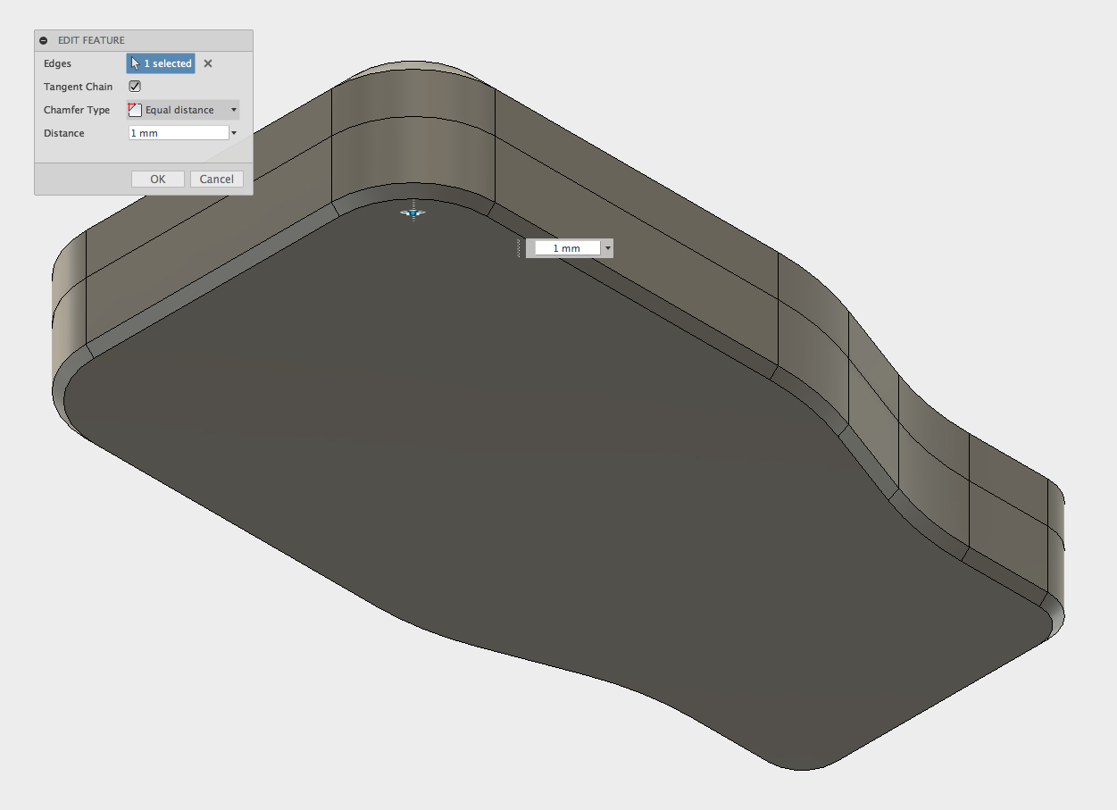
We now have 2 separate Bodies that make up the halves of our enclosure. Another 1mm Chamfer is then added to the bottom of the 2nd body.
 Adding Chamfer to bottom edge.
Part 2 - Cavity
The next step is to create a cavity inside the two Bodies that will contain the circuit board and electronics. Currently both Bodies are completely solid as shown in this section view.
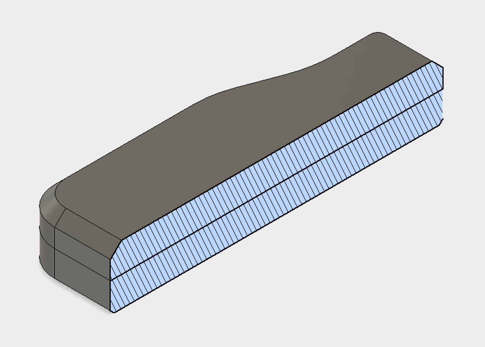 Section view of 2 main bodies.
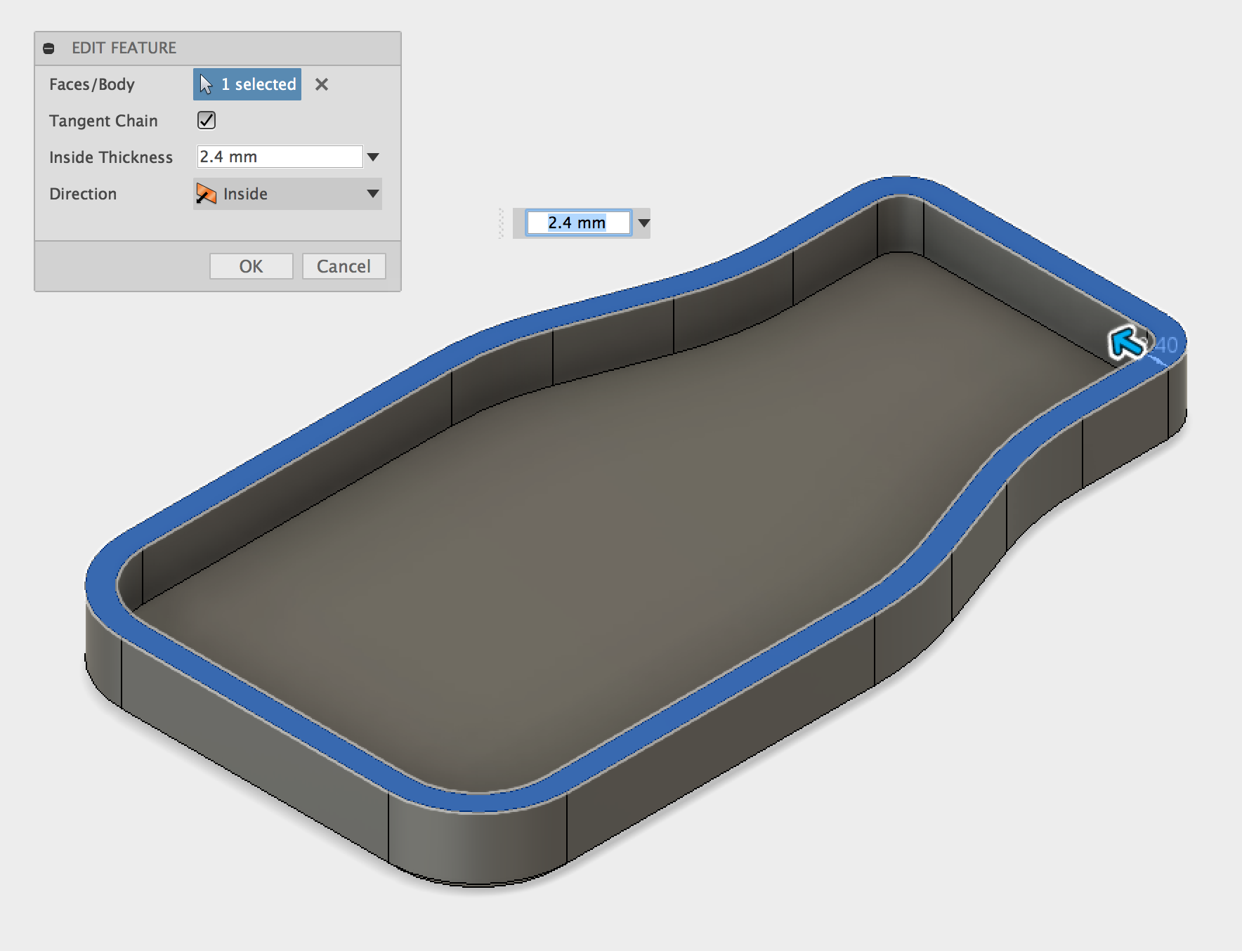
Luckily the Shell tool makes this very easy, just select the faces that need to be removed and define a wall thickness to create a cavity inside the enclosure. The image below illustrates what the Shell tool does. It may be necessary to hide one body to be able to select the face of the other and vice versa. This can be done by right clicking on the body and selecting Hide.
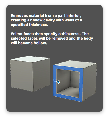
Hint: If you hover over a tool icon in Fusion a little pop out explanation will let you know what it’s for!
 Body after being shelled.
Now we have a cavity inside both halves with plenty of space for our circuit board assembly. Using the Shell tool is a much more efficient way of modeling enclosures, especially when creating more complex designs.
Note: For FDM printing a 2.4mm wall thickness has been used for this part. It is a good idea to think about printing parameters while designing parts, using a wall thickness that is a multiple of the nozzle size will result in a much better print. A 0.4mm nozzle is going to be used to print this part so a wall thickness that was 6 x the nozzle size was selected (0.4mm x 6 = 2.4mm).
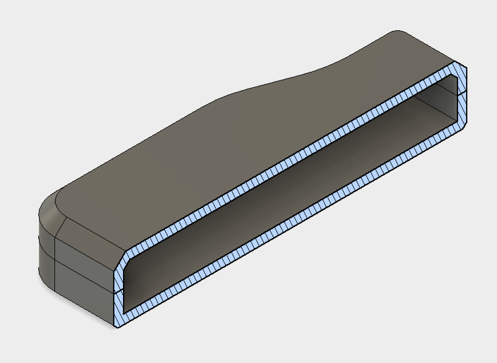 Section view of shelled part.
Part 3 - Buttons
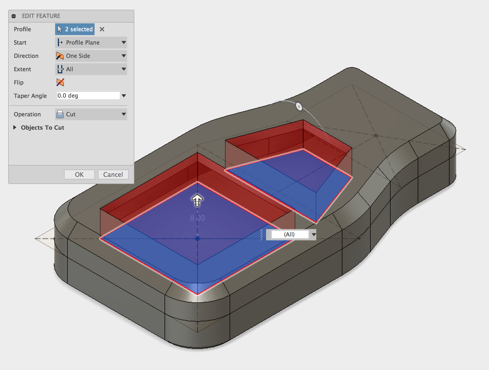
The next stage in the enclosure design is to cut out the spaces for the push buttons. The profile for these were created in the first sketch. This sketch may now be hidden and will need to have it's visibility turned back on. A simple Extrude Cut will be used to create the holes for the buttons. Instead of specifying a distance the Extent - All option can be used which will cut away anything blocking the path of the profile.
 Extrude cut for the button cut-out.
Fillets were then added to round off the sharp corners, this time using a 2.5mm Fillet for all edges.
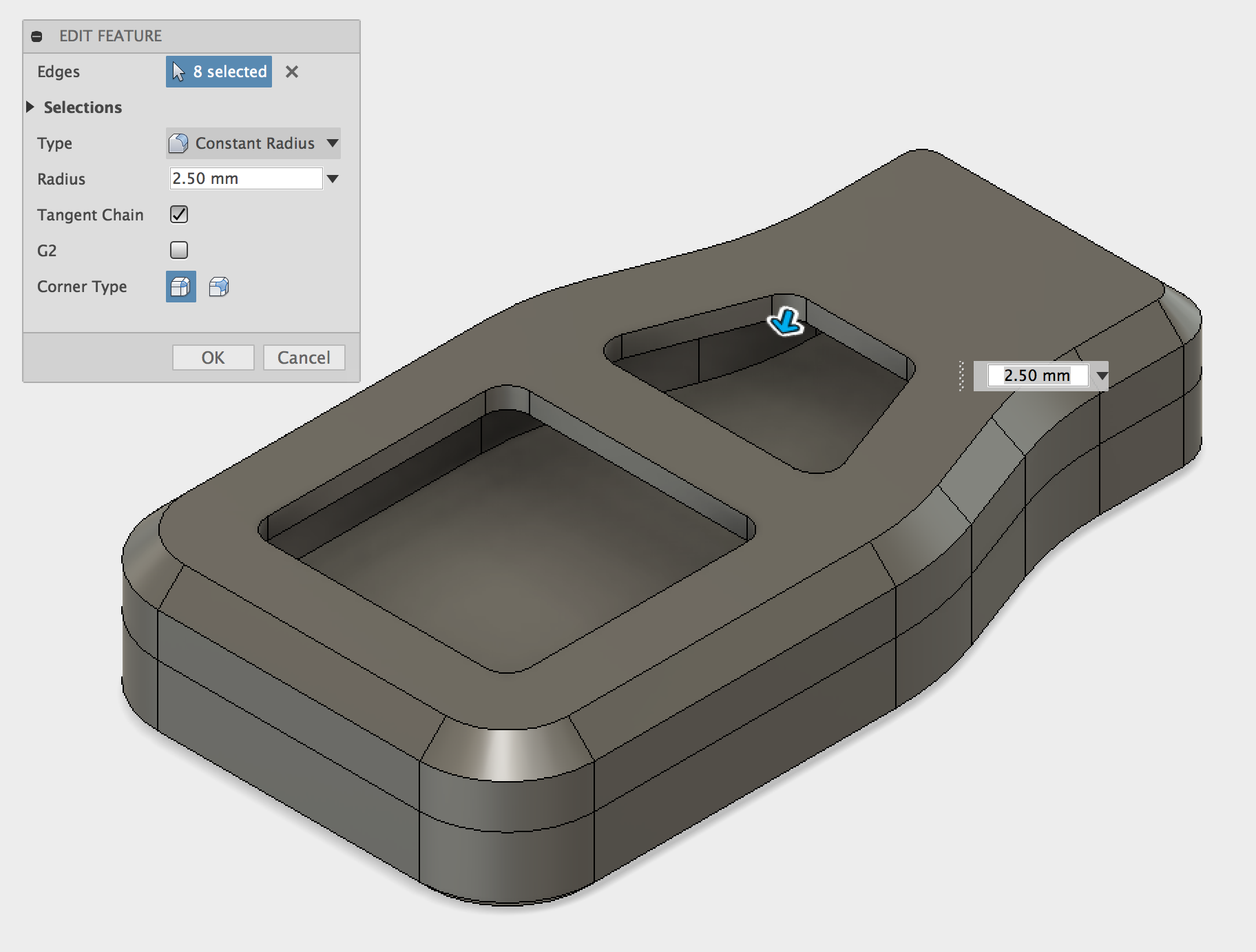 Completed fillets.
The top surface of the top half of our enclosure can now be used as a plane to create the sketch for the buttons. It is also possible to Project the existing geometry into the new sketch which is a big timesaver. In addition the Projected geometry will update to reflect changes made to the part. For example, if the button size was changed from the first sketch the buttons would automatically update to reflect the changes.
A purple line represents a Projected line, which references existing geometry. The blue lines are lines that have been Offset from the Projected lines to a specified distance. To ensure the button would fit into the case the button inserts was made smaller than the cut-out. This 0.5mm clearance is to allow for deviations in size of the button. The outer edge of the button was also offset by 2.5mm which will become the main body of the two buttons (as shown by the dimensions in the image).
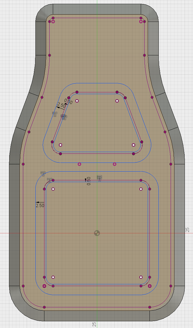 Sketch showing button layout.
Note: When 3D printing, or in any type of manufacturing nothing is ever exactly the correct size. This deviation from the nominal size is known as the tolerance; a range of values that define if the part is acceptable or not. Usually the more precise a part is the more expensive it is also. For FDM printing, Protolabs Network have an acceptable lower limit of 0.5mm for dimensional accuracy.
The internal part of the buttons can now be extruded down. As these buttons will be printed separately using a flexible material, they are created as a New Body. The distance used for this is -2mm which builds the body down into the button cut-out that was created earlier.
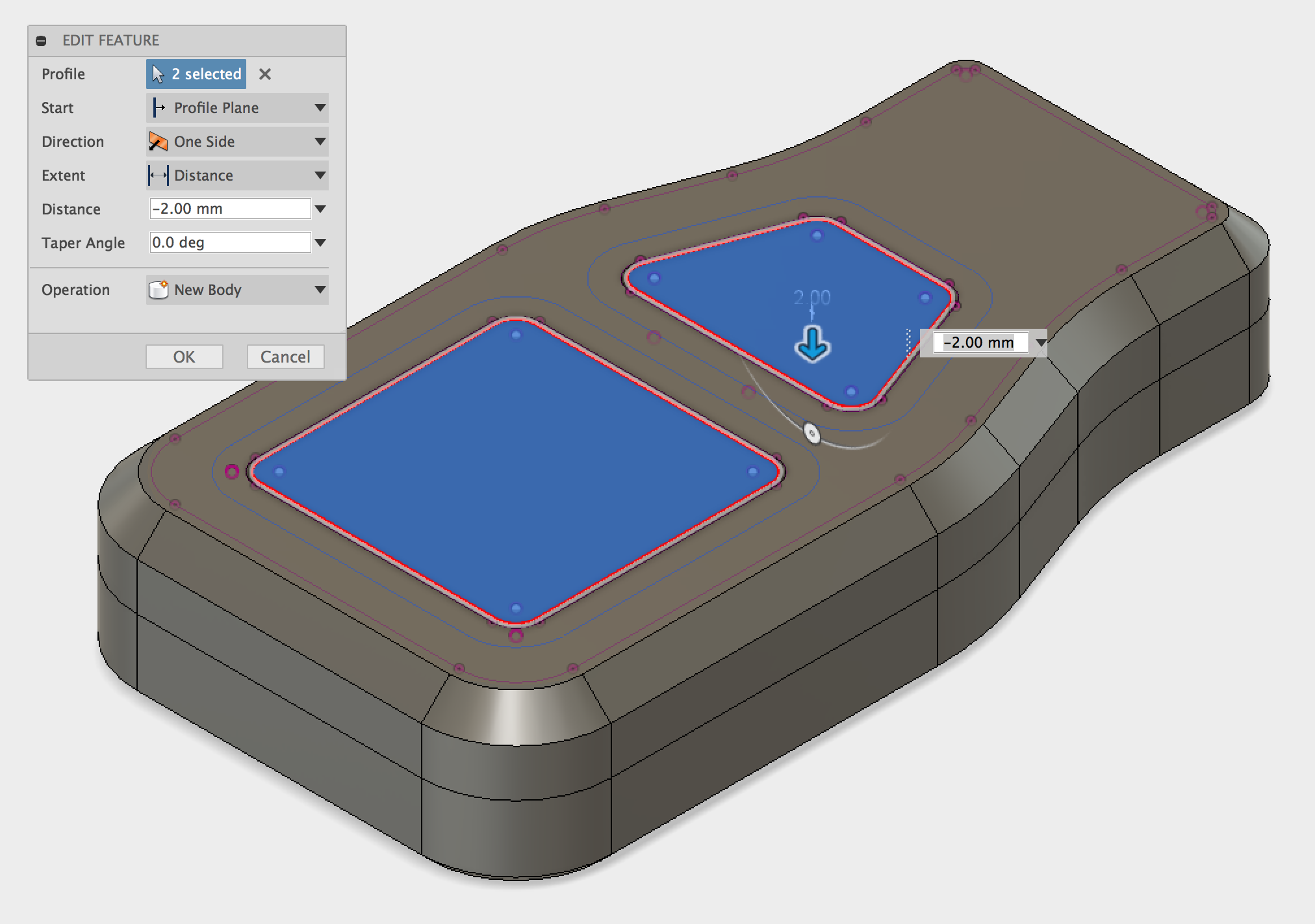 Button being Extruded down.
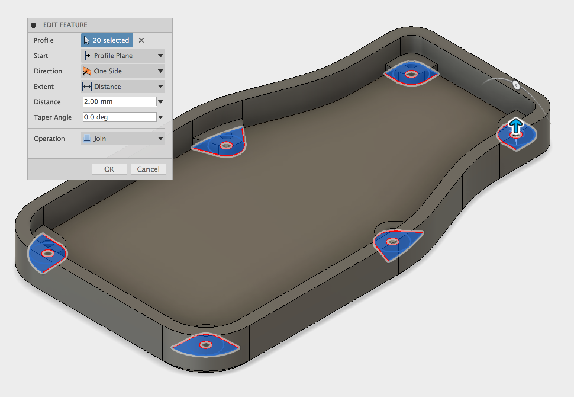
The sketch can again be reused to Extrude the profile 2mm for the main button body. This Extrude Cut operation should Join to the base of the buttons that were just created, however this will result in the buttons being joined to the top case part. To prevent this, the visibility of the case top part can be turned off during the Extrude Cut operation, then toggled back to visible when complete.
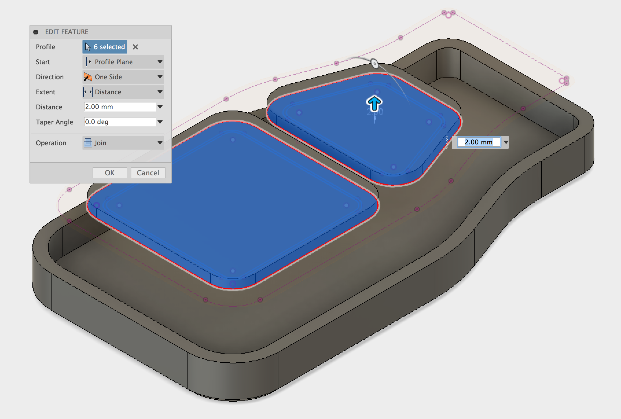 Button being Extruded up.
Some aesthetic features can now be added to the outer profiles of the buttons. In this case a simple Chamfer is used with a distance of 1.5mm.
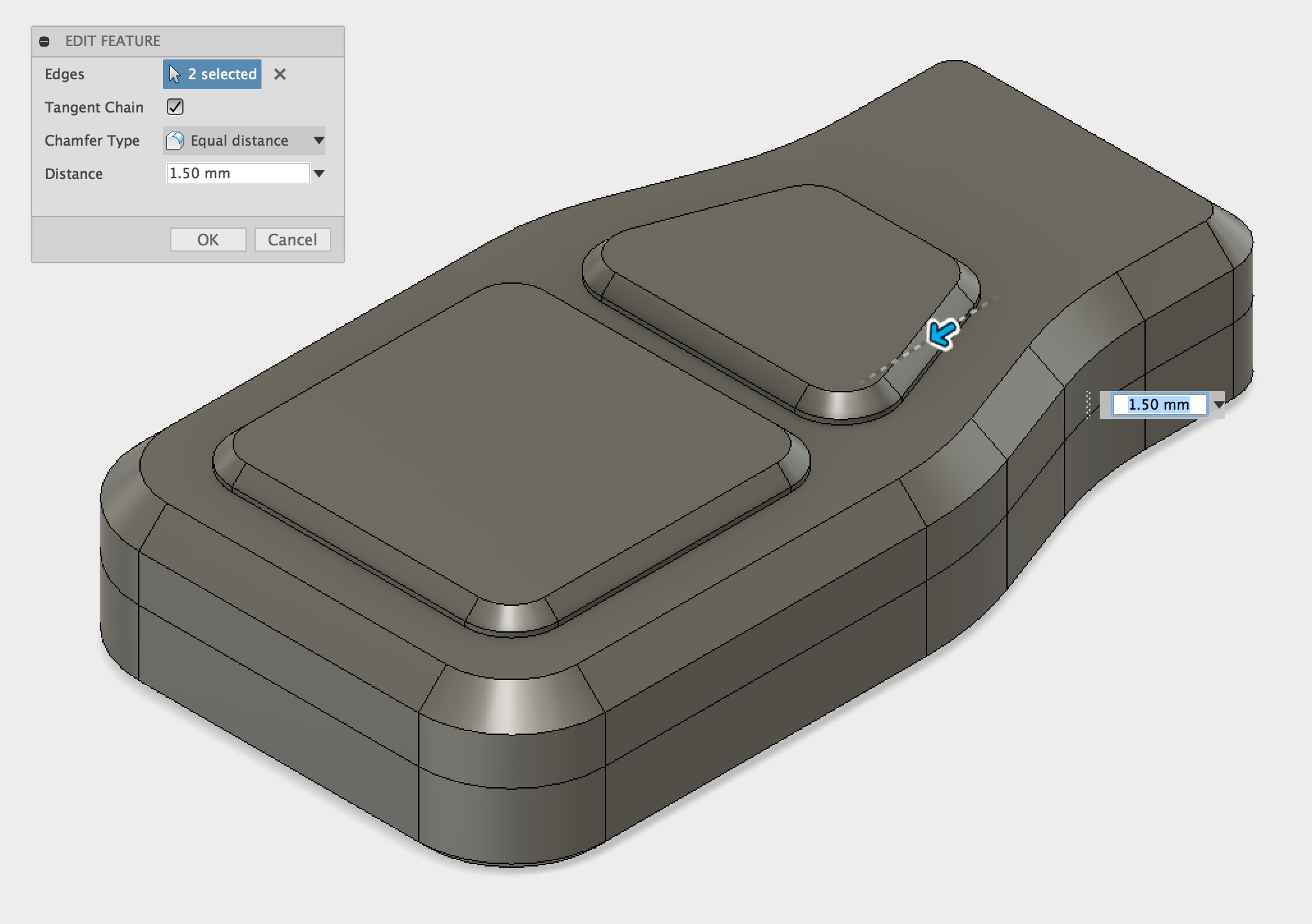 Chamfer being added to the buttons.
The section view shows the 4 separate bodies; the top & bottom half of the enclosure, and the two buttons.
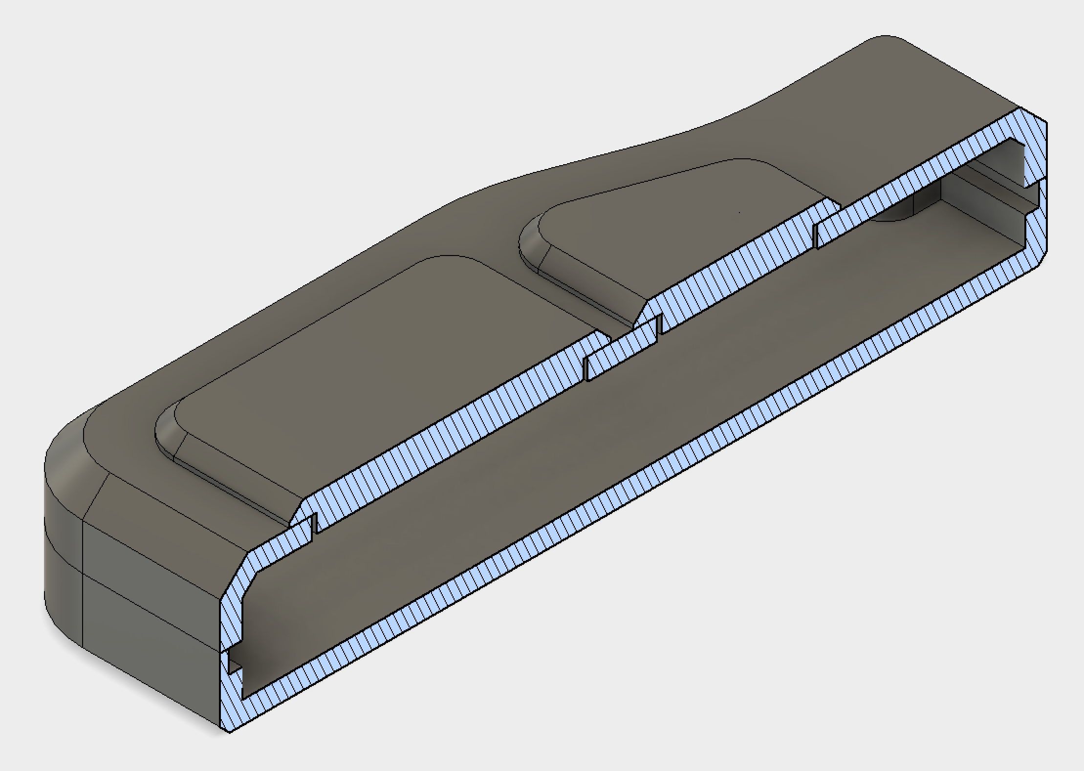 Section view showing buttons.
Part 4 - Circuit Board Mounting Bosses
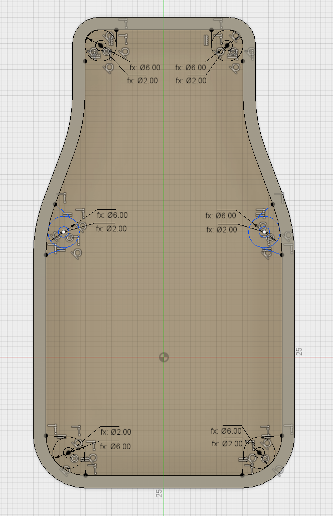 Sketch for mounting bosses.
The main purpose of this part is to enclose a PCB (printed circuit board) and electronic components for the remote control. To mount the PCB securely inside the case, bosses are used as a mounting point for securing the board. A number of fastening methods can be used for 3D printing.
For this design, self tapping screws were chosen as a simple and cost effective solution, used to screw into the bosses and clamp down on the PCB. M2.5 screws will be used so the holes need to be slightly smaller than the screw (0.25mm undersize is a good rule) to allow the threads to cut into the mounting bosses. For extra strength and rigidity, extra material is added to the sides of the bosses anchoring it to the side walls. This also makes the features easier to print and provides a better finish as stringing issues during printing are reduced.
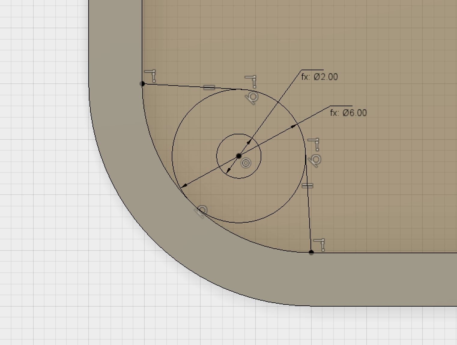 Sketch for mounting bosses.
The profiles can now be Extruded by 2mm to create the boss. By excluding the hole profile from selection creates a mounting surface and hole in one go.
 Boss features being extruded.
Part 5 - Lip
To ensure that both halves of the case fit together a lip is added. This helps with alignment, reducing the chance of gaps between the halves and in addition greatly increases the rigidity of the assembly.
To create the lip feature the top part is temporarily hidden. It is then possible to create a sketch on the top of the bottom sections wall by offsetting a line 1.6mm from the inside edge. An Extrude Cut is then used to cut down into the wall by 3mm creating the recessed part of the lip feature.
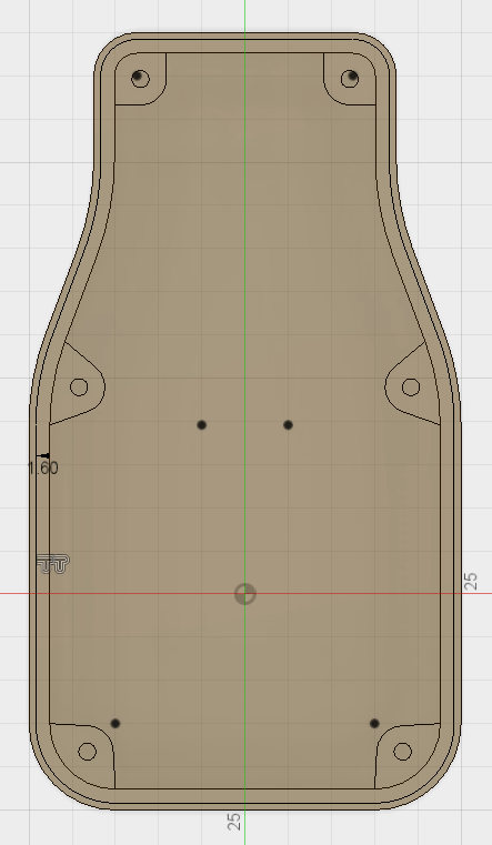
Sketch showing offset lines for the lip feature.
Note: As mentioned earlier it is good design practise to use a wall thickness that is a multiple of the nozzle size. 1.6mm was used for the offset including 0.4mm for a tolerance allowance.
 Lip Extrusion.
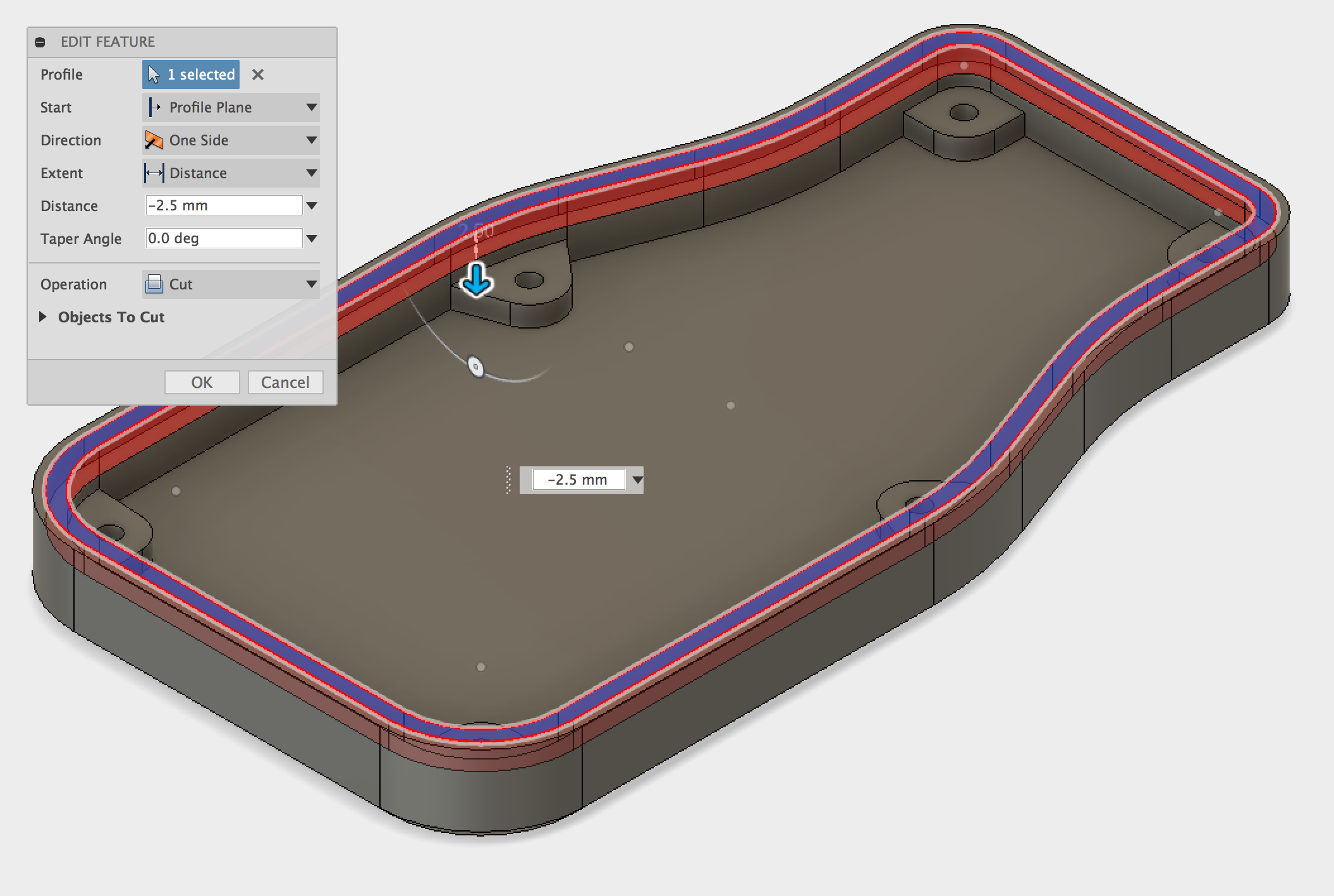
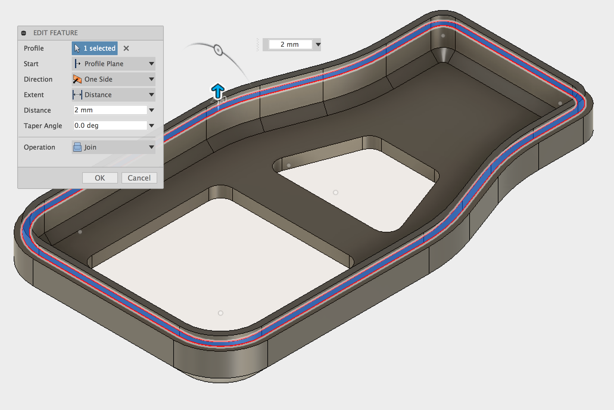
The same steps are then applied to the other half of the enclosure, this time using a sketch offset of 1mm and Extruding a profile of 2mm, this time using a Join operation. Again, a tolerance of 0.5mm is used (the top half has an Extruded Cut of 2.5mm with the base having an Extruded Join of 2mm leaving a 0.5mm gap between the 2 lips).
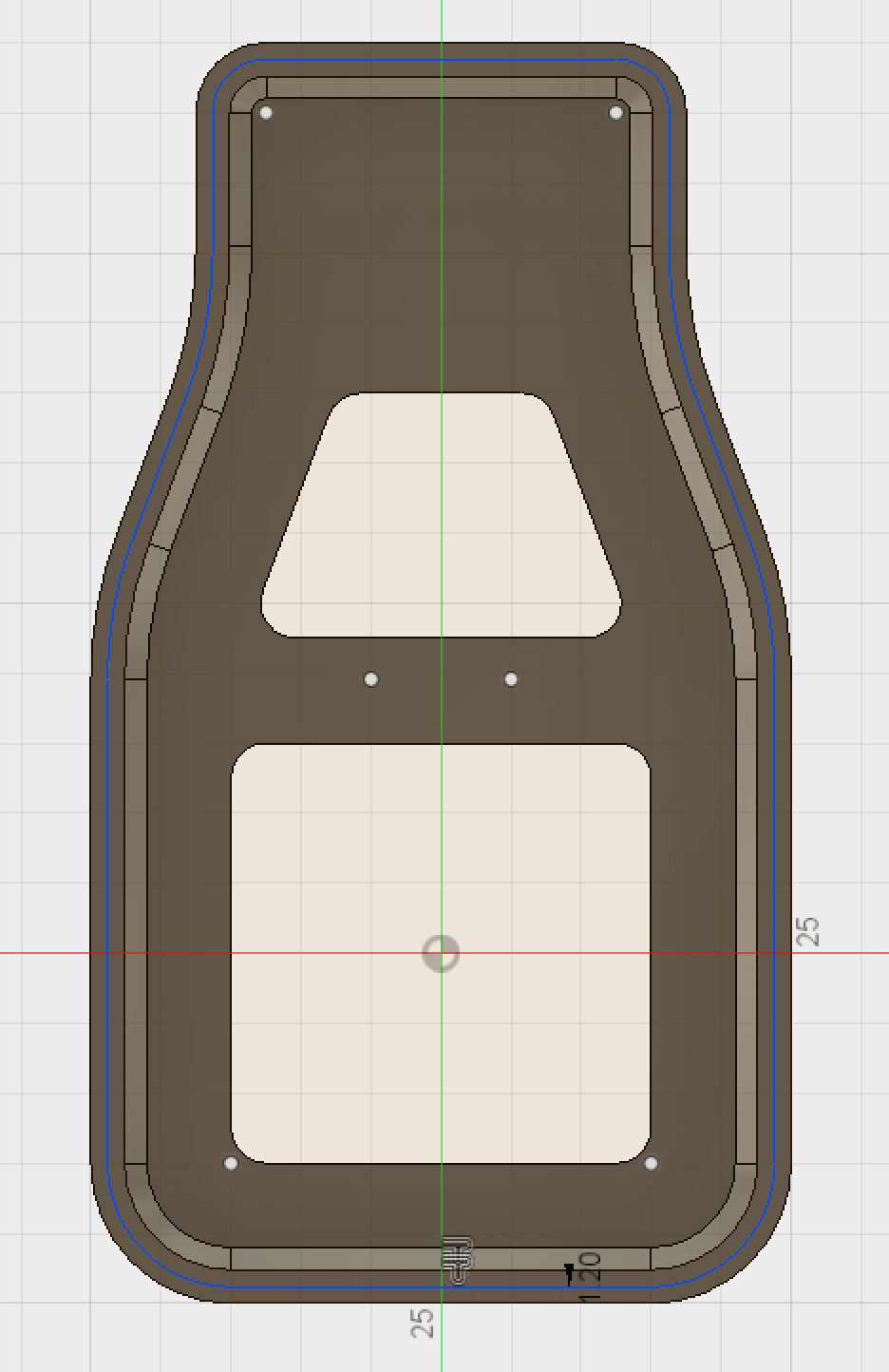 Sketch showing offset lines for the lip feature.
 Lip Extrusion.
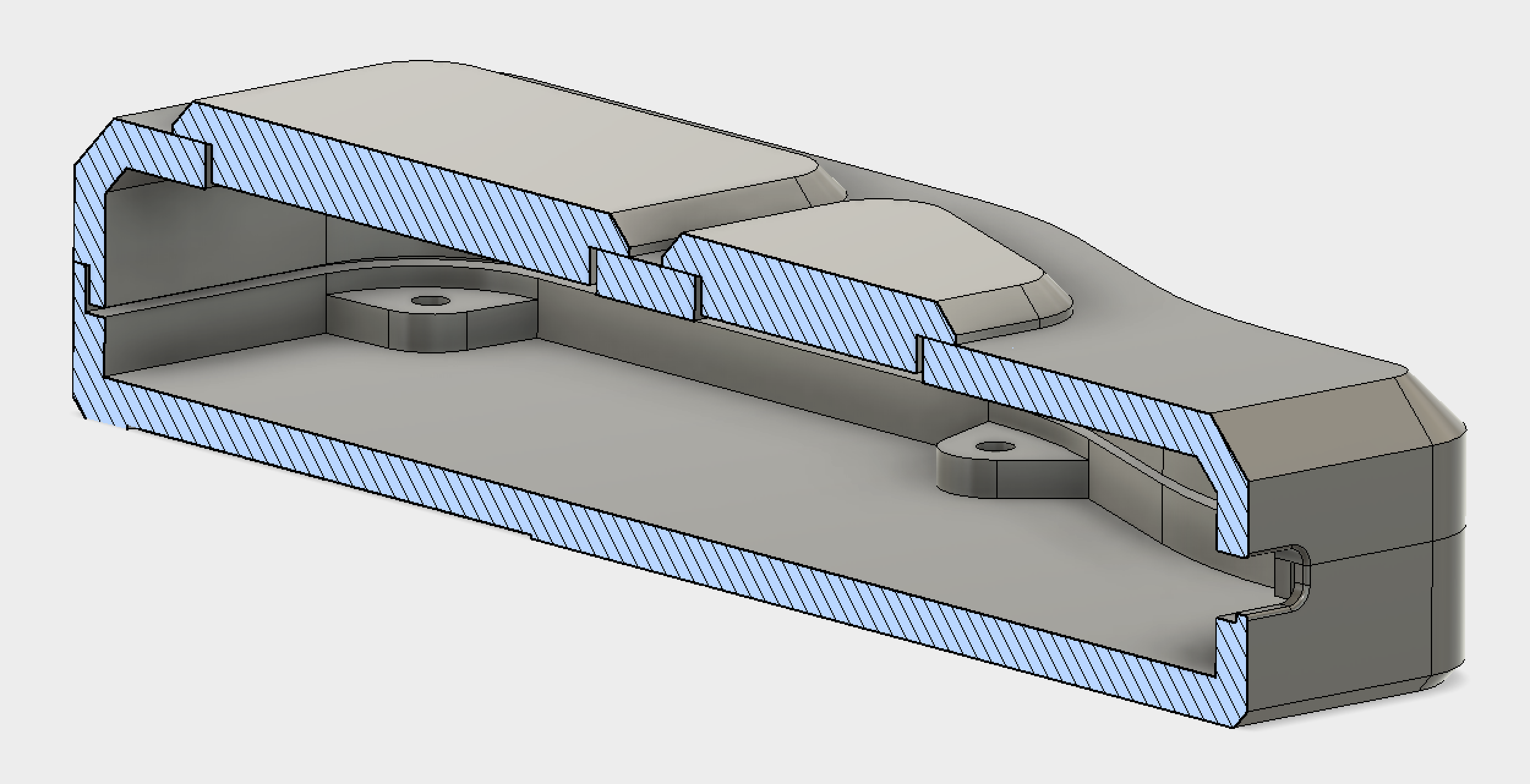
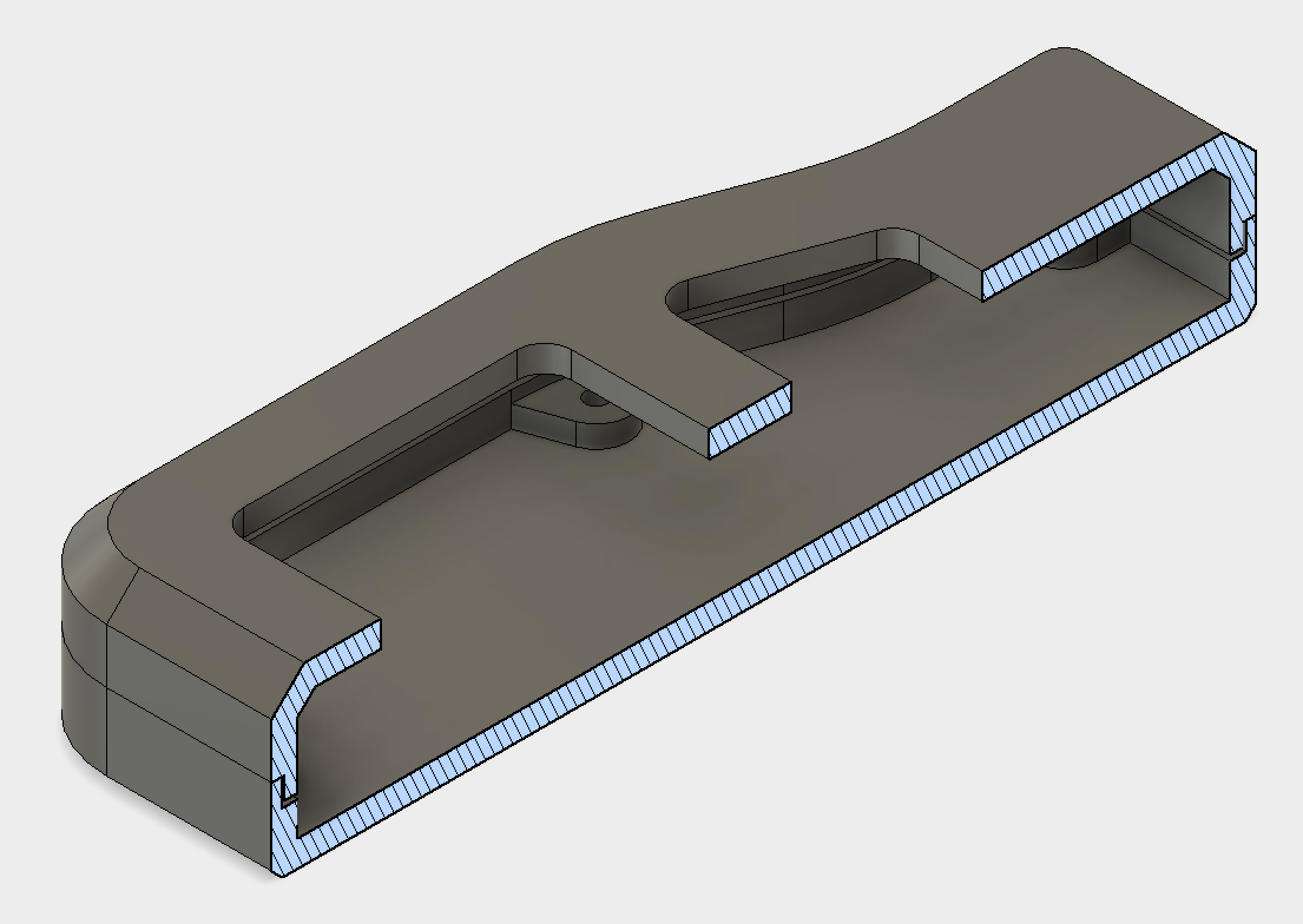 Section view showing Lip feature.
The section view shows the tolerance around the lip that was left to assist in the alignment and assembly of the 2 halves..
Part 6 - USB Connector
The final stage of the enclosure design is to add the cut-out for the micro USB connector. A basic Center Rectangle is used, with enough clearance for the connector to fit. The sketch dimensions are included below.
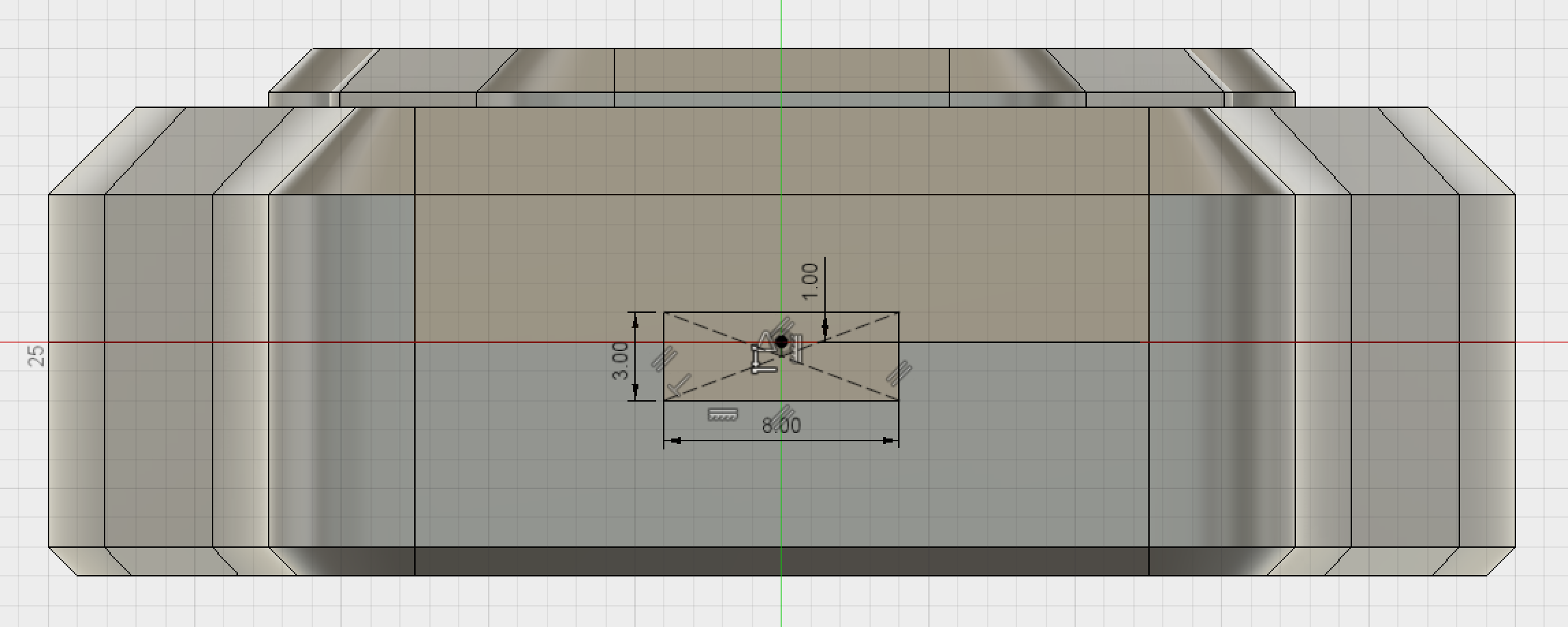 USB connector cut-out sketch.
The profile is then Extruded Cut through the two bodies. Fillets are added to improve the appearance of the cut-out and to reduce stress concentrations.
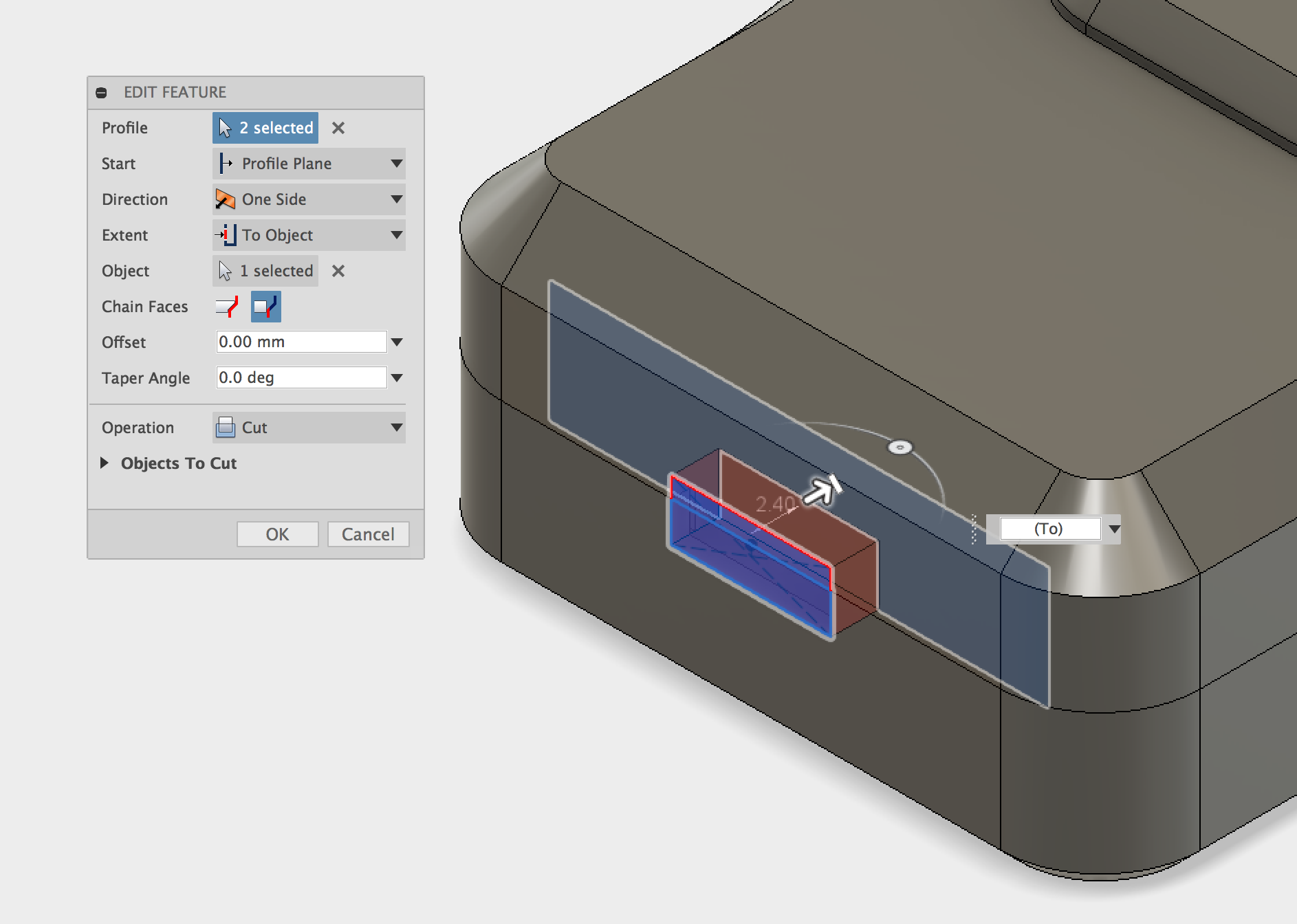 USB connector cut-out Extrusion.
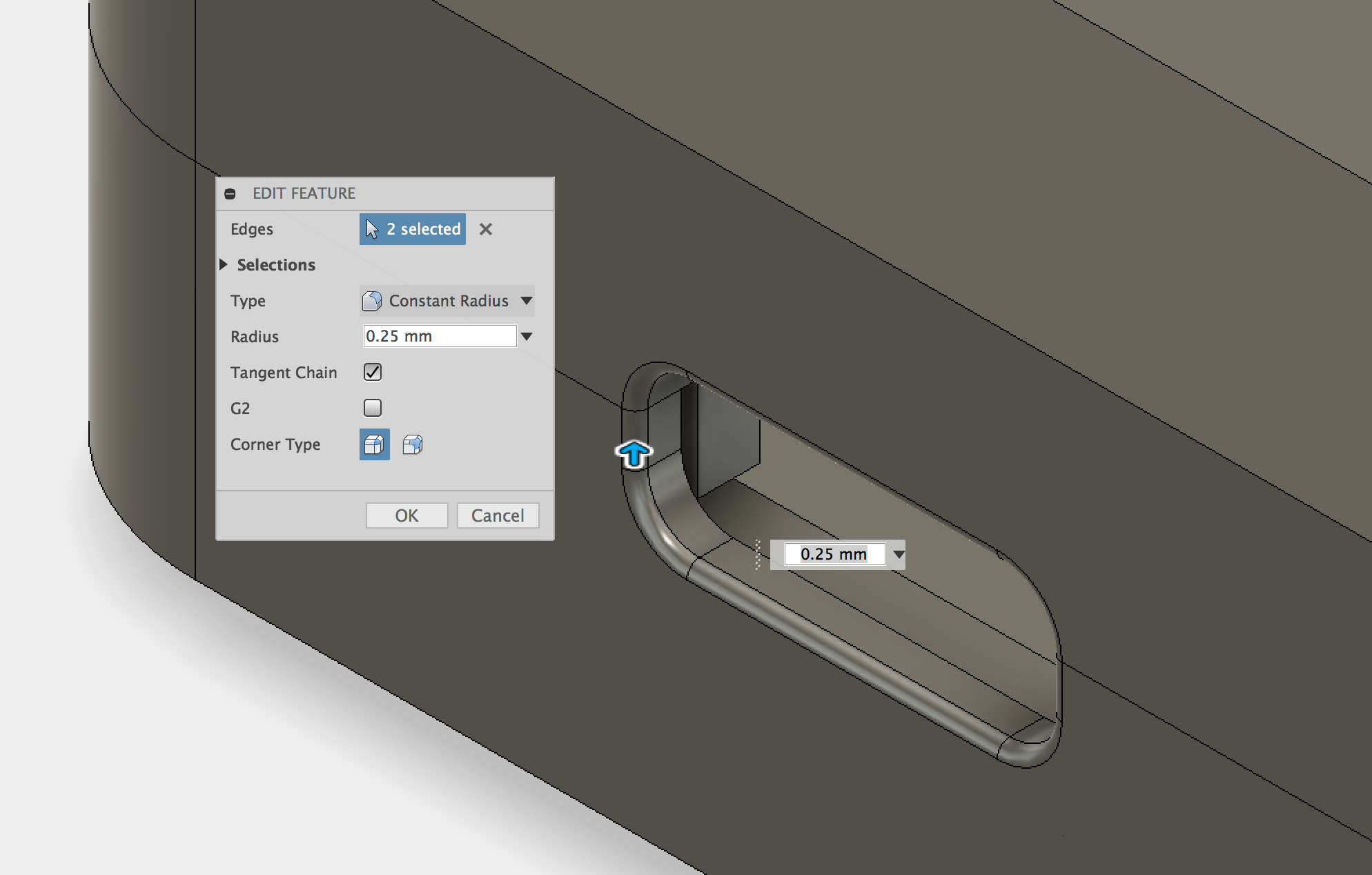 USB connector cut-out fillet.
Part 7 - Logo
To add some branding to the case the Protolabs Network logo has been included. It is easy to use an SVG file to import the logo without needing to sketch it manually. A sketch is created on the bottom of the case, and the SVG tool is used to import the logo. It is then positioned in the desired location. The insert SVG tool can be found in the Insert menu. You can download the Protolabs Network logo as an SVG here.
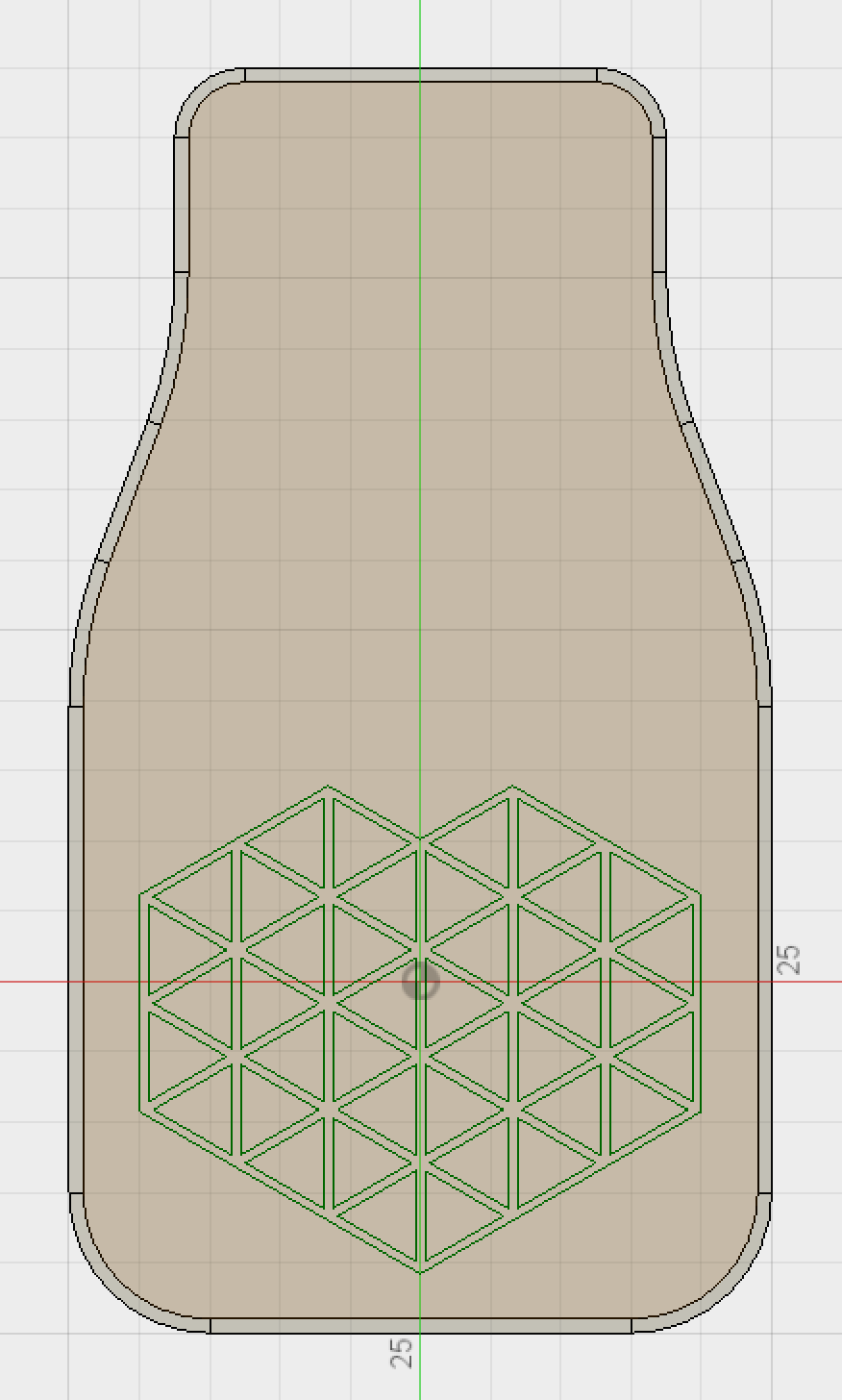 Sketch showing imported SVG.
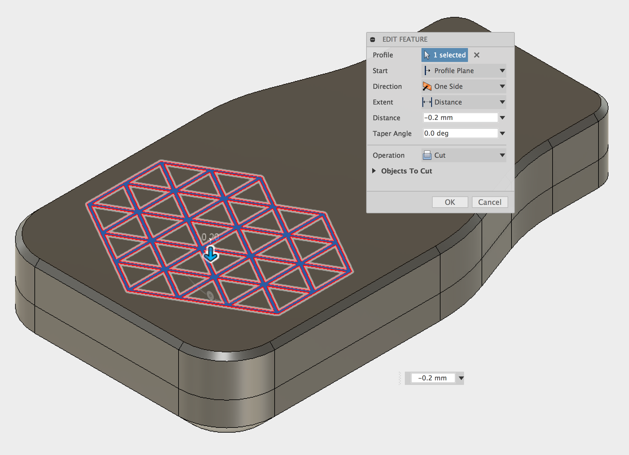
The profile is Extruded Cut -0.2mm which will result in 2 layers when printing at 100 micron resolution. As this face will be located in contact with the print bed during printing, support material should not be used here as it will result in a poor finish due to the small features. By only using a 0.2mm cut the logo will be visible and sharp without any sagging from the unsupported overhang.
The enclosure is now complete, comprising of four separate bodies; top & bottom case halves, & the two buttons. If you would like to take a more in depth look at this model you can download the Fusion 360 file and also the STL files. There's a more in depth look at 3D printing for enclosures on our Knowledge Base found here.
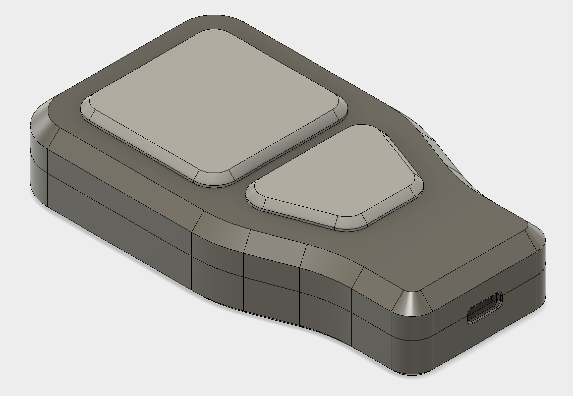 Finished enclosure assembly.
 Finished enclosure assembly section view.
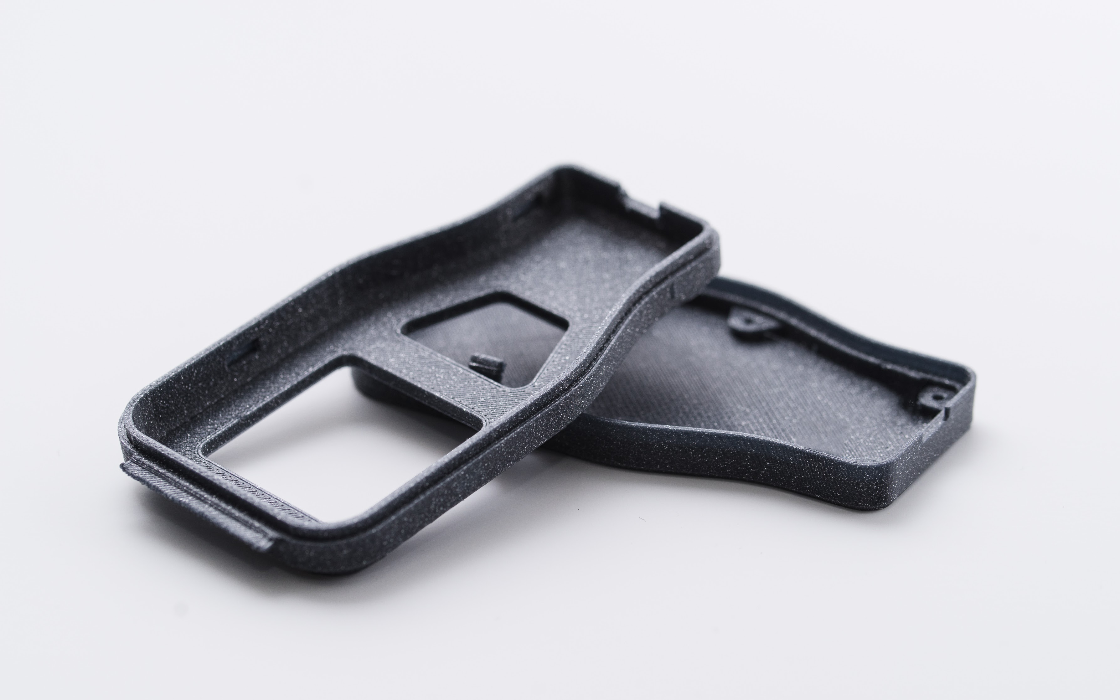 Final print of the two enclosure parts.
Learn more from our in-depth 3D printing guide here.