


The Protolabs Network Standard
Tolerances and Dimensional accuracy
This page describes the standard tolerances and dimensional accuracy for injection molding that our manufacturing partners adhere to. If the technical drawing does not specify tolerances for a given part, then the standard tolerances section below is the reference for our manufacturing partners.
Standard tolerances
For general injection molding projects, unless otherwise specified and agreed, any undefined or non-toleranced dimension in the technical drawing will follow the DIN ISO 20457:2020 TG5 class tolerances.
The table below defines the general tolerance for a given nominal dimension range.

Code letter:
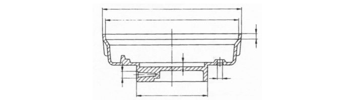
B refers to mold related dimensions, as shown on Fig. 1. These are the dimensions in the same part of the mold.
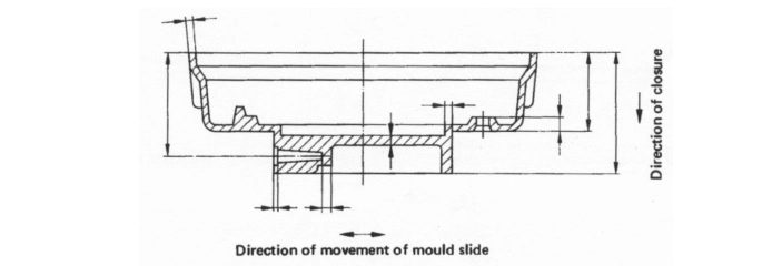
A refers to non-mold related dimensions, as shown on Fig. 2. These are the dimensions determined by the interaction of movable elements of the mold (for example wall thickness or bottom thickness, or any dimension determined by the shims or mold slides).
Concentricity and roundness
Concentricity and roundness follow SPI Standards & Practices of Plastic Moulders, 1998 edition.
The standard tolerance on concentricity is +/-0.125 mm.
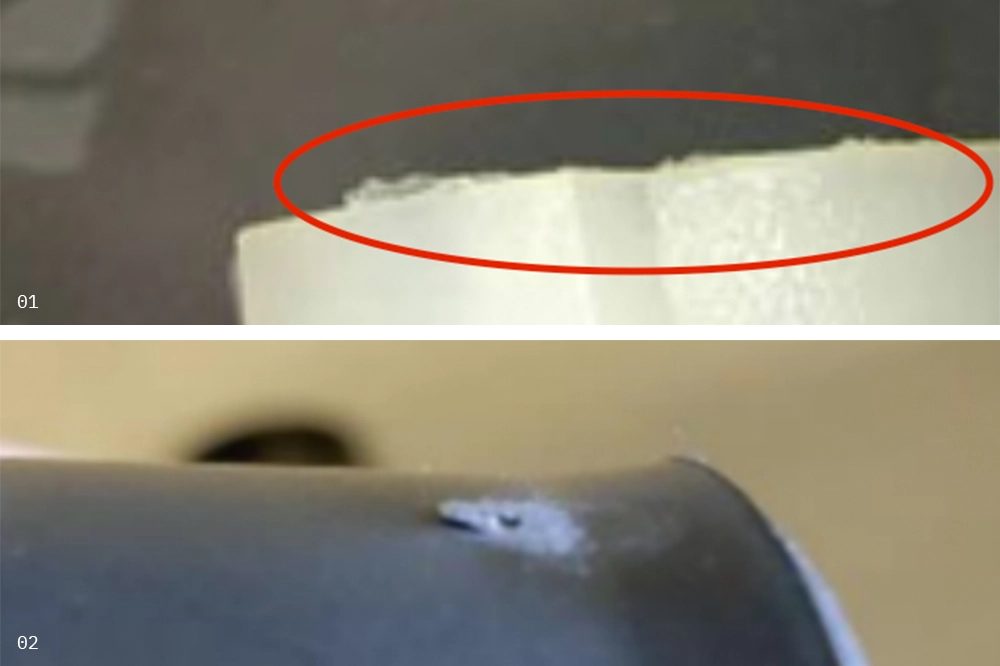
The standard tolerance on roundness is +/-0.175 mm. A visual example of "out-of-round" is shown below.

Flatness tolerance
For dimensions up to 100 mm, the standard flatness tolerance is +/- 0.400 mm.
For dimensions above 100 mm, the standard flatness tolerance is +/- 0.800 mm.
Marks on the surface of a part
This section describes the tolerance on marks visible on the surface of a part.
If our manufacturing partner expects marks to be present on a part, it is necessary to include its location and associated tolerances in the DFM for approval by you, the customer.
Flashes
Flashes dimensions should not exceed 0.125 mm on any part in any direction.
Ejector marks
Ejector marks should not exceed 0.125 mm.
Gates and runners removal
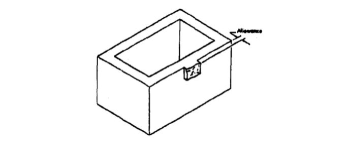
The acceptable protrusion or divot when removing gates and runners is defined by SPI Standards & Practices of Plastic Moulders, 1998 edition.
For any method of gates and runner removals (breaking, clipping or machining) the standard tolerance is +/- 0.125 mm.
Inserts
You can request branded inserts in an order. For every order requiring inserts, the Manufacturing Partner needs to clearly specify if they use a branded insert or another equivalent.
Flashes are removed if inserts are moulded into the parts, with a tolerance of +/- 0.125 mm as specified in section Flashes.
Get your parts into production
Get an instant quote