hi,
i’m using a 12v @15amp power supply to power up my appliance.
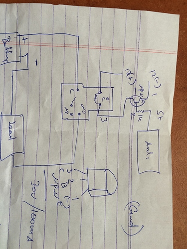
i will need to cut the power for some time and then let it flow again. For this, i’m using this relay and this transistor (NPN), and this is how im wiring it up. (picture below). I’m using the same power supply for both relay and appliance. But when i powered it up and set the arduino pin to high, It didnt work. I’m sure that the relay is working because when I power it up separately, I can hear a “click”. Is the type of transistor i’m using ok? Or is the resistor connected to the base too high that the circuit isn’t being completed?
Can someone please tell me what i’m doing wrong?
Thanks a lot. Mitch
1 Like
You should better use a MosFETs that an npm transistor
Invize
3
You can’t mix voltage levels like that with bipolar transistors. You’re effectively applying 12V directly to the Arduino input and that could burn burn the pin circuitry or even the entire chip. Also it won’t turn on the relay.
This circuit could be fixed using an additional bipolar transistor, but as as strawmedia says it would be easier to use a MOSFET transistor. If you replace the transistor in your diagram with a N-channel MOSFET it should do the trick. Equivalent connection: source=emitter, drain=collector and gate=base.
Also you definitely want to add a fly-back diode across the relay (true for all transistors) to protect the transistor. Just place a diode in reverse across the relay and this will short out any reverse current generated by the coil when the transistor turns off. A coil works sort of like a capacitor, except with current instead of voltage so when disconnected it will try to discharge it’s current generating very high voltages which can fry most semi-conductors and you don’t want that obviously. Pretty much any silicone diode will work.
As said, a MOSFET is usually more practical for such applications, but a NPN should work too with the right network. The circuit you have limits the base current, but not the collector-emitter current, because there is no collector or (better) emitter resistor. Another factor to consider is the voltage between the base (defined by the Arduino) and the 12(-). First of all, is the 12(-) actually the GND? and is the GDN common between the Arduino and the power supply? If this is the case, then you are actually applying 5V and the current is (5 - 0.7)/1k = 4.3 mA. If the GND is not common, then you should make it common. You can also measure the voltage between the Arduino and the 12(-) and calculate from there, but in any case this would not be a sound approach.
If you can get hold of an n-channel MOSFET you life becomes a lot easier, no gate current, just the threshold voltage to take care of and it’s a somehow more robust solution, considering it’s just switching on/off. The relay coil and the MOSFET have very low resistance, so putting a limiting resistor “ahead” of the transistor will allow for a smaller transistor (less than 15A, more than coil rated current), protect it from blowing and your home from fire (15 Amps on a short can make some nice sparks).
Hope I was clear enough 
p4prix
5
Just connect 12V(-) with arduino GND (to make common ground) and it should work just fine. In addition connect common rectifying diode to relay coil (in antiparalel) to catch de-energizing spikes.