jjenco
1
Hi, I’m experimenting with my new RostockMAX v2 printer using SeeMeCNC ABS filament. The attached file shows two issues I’m trying to resolve.
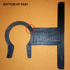
First, the sides of the model are printing nice and smooth, but the bottom (shown) and top are not finished well at all. The top is only slightly better (smoother) than the bottom. I’m printing with a 0.3 bottom layer, a 0.2 layer setting, and perimeters set at 3mm. What can I do to get a nice finish on the bottom and top?
Second, the circled area shows a gap in the fill that also results in a gap most of the way around the circular latch portion of the part. I wanted this to be solid, as well as the ‘T’ crossbar portion of the latch. The circular part thickness is 0.125" (3.1mm) and the crossbar thickness is 0.25" (6.4mm).
Thanks for any suggestions, tips, or tricks you can provide!
John
1 Like
I think i see 3 shells?
Try with 2 shells there might be too little space with 3 shells then your minimum line size of 0,5 might be causing gaps
It looks like it’s possible an error in your slicing software. I suggest you watch this video as it explains about how the slicing software works on making decisions in special circumstances where there may not be enough space to accurately print infill compared to the diameter of your nozzle opening.
That video specifically mentions printing thin walls, but the same issues can apply to the internal parts of a print where the slicing software may possible skip over areas as it could not fill it in properly.
I’ve never had this happen personally, but I would also suggest checking your bed levelling as this can cause an array of issues even when it is just slightly off.
As well, it appears you have selected several outer shells, possibly 5 or so? This can cause a problem as in the outside bit as well as the T, where there should be Infill, the slicing software has avoided it as it does not recalculate after making the outer edges where additional infill is needed. I’d suggest trying again with two or possible one outer shell and get back to us with the results!
Pepstick and Zettlinger are right and reduce layer to 0,15mm, if you have a choice try a full honeycomb infill af 85% and 2 outerlayers
About smoothening is just grinding it a little bit and then an acetone treathment and it will become very smooth!
jjenco
7
Thank you all for the various tips and suggestions. I’m using MatterControl slicing software and I don’t think there were specific settings for ‘outer shell’, unless that is what MC refers to as ‘perimeters’, in which case those were set to 3mm.
I’ll post next week after I try some of your suggestions.
Thanks again!
JJ
Ok if you layer height is 0,15 mm and then outershell perimeter should be somewhere around 0,3 or on the save side ,4 mm
Hi, sorry do not agree with everything written so far; a number of things. Firstly your wall/shell size needs to be a multiple of your nozzle size. So if you have a 0.4mm nozzle then 0.8mm,1.2mm,1.6mm,2.0mm.2.4mm etc. I am inclined to say it is better to use even numbers, 0.8mm (2walls) 1.6mm (4 walls) but I have never done any real testing on this and have used 1.2mm without a problem. Number of walls; think someone has already mentioned this, but use 0.8mm an infill the rest which hopefully will resolve your “hole” problem. On surface finish well a variety of things can affect this. Generally the slower you go the better the result. You do not mention your print speed but if you are looking for a good finish I would not go above 40mm/s and personally if I am after as good as I can get I will use 20mm/s or 30mm/s. Your hardware and its alignment and setup will also impact the quality. On the first layer then additionally setting the correct distance between the bed and the nozzle is absolutely vital; repeat that sentence 3 times.
1 Like
It looks like you are printing with too many perimeter shells…try reducing those down to 3 or 3 shells and you shouldn’t have the gaps in your print. Also, 20-40% infill is a good standard to use
davek
11
Re your print - you have too many outer perimeters. I mostly print with 3 outer perimeters. In Slic3r and Simplify3D (and Cura I think from memory) you can just set that as a value. If you can only set your outer shell value as a distance, then you need to know what your extrusion width is in order to calculate what 3 perimeters would be. If your nozzle is 0.4mm (pretty standard) then your extrusion width will probably be somewhere between 0.48mm and 0.68mm. (Note: I disagree with the poster @Craig_7 who says it is 0.4mm) When a layer is deposited the extruded material is slightly squished by the nozzle against the previous layer or bed and also against the adjacent material from a previous extrusion on the same layer. You don’t want it to be 0.4mm because then there would be hardly any material touching the adjacent lines and you can easily get delamination (ie: they won’t stick very well).
For a 0.4mm nozzle, Simplify3D auto sets to 0.48mm width. Slic3r auto sets to 0.68mm width. Both can be overridden to customise. For your little part try 0.9mm-1.0mm as your outer perimeter. Also, you may want to try some other (free) slicers like Slic3r, Cura and also have a look at Repetier (uses Slic3r or Cura engine but good interface). It is very interesting and good experience to learn how different slicers will produce the same part and then you will also learn for tricky parts which software will best make the part.
Lol I have to disagree with poster Davek,.68 for a .4 nozzle is insane. Now just maybe this may have something to do with slicers. On the Ultimaker forum most people use Cura, as do I. The forum is absolute that that if you have say a .4 nozzle you set wall widths to multiples of .4 To do otherwise presents problems to Cura. Maybe it is OK in the slicers Davtek quotes, but not Cura. Oh and in nearly 3 years I have never once suffered delamination, the idea that using wall widths of multiples “easily” leads to delamination is ridiculous.
Now, very recently there has been a discussion on variation of the nozzle size statement (and the wall width correspondingly so it remains a multiple) to improve 1st/top layer performance. I did some testing two weeks ago on this. Setting the nozzle width to .45 gave clearly worse results than leaving it at .4. Very marginal but I am convinced at the moment that setting it at .35 gave a better result than 0.4. What if anything it does to dimensional accuracy (important for engineering, maybe not for figurines) I have not yet tested.