Greetings all,
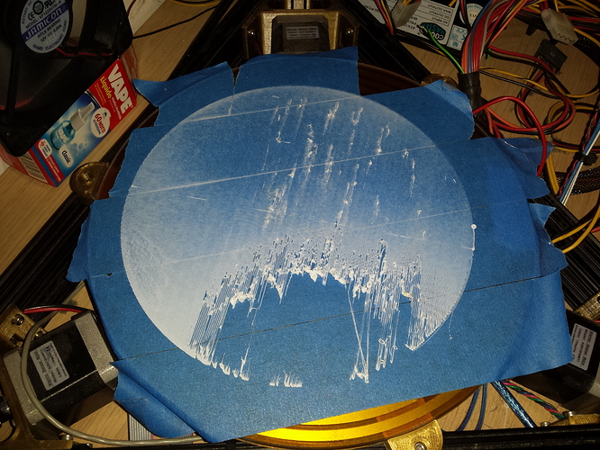
I bought a Kossel XL last year from builda3dprinter.eu. Unfortunately I’m having a lot of problems with calibration. To be exact it will work so-so for small prints, but when it comes to larger footprints, it fails miserably. I’m attaching a photo to illustrate my problem. I calibrate each tower and the middle of the platform, using the paper test, and those are fine. Even then there is this “dimple” having a whopping 0.15-0.2 mm gap there…Currently I’m trying rotating the platform to see if this issue is with the movement or with the glass somehow…I mean this is not a concavity/convexity problem nor is it a simple “tilted plane”, and thus calibration simply doesn’t help with it…Any suggestions would be appreciated. Btw, the issue is the same without the masking tape, using the heated bed. Thank you!
1 Like
.15 to .2 mm gap is not unheard of. Glass isn’t '.00000001mm ’ perfect. Mirror glass is usually better. I suggest rafting large prints, and over extruding on the first layer an additional 25% or more
Hi Adam,
I have a delta too and the issue is familiar. For me the purchase of a borosillicate glass bed solved the issue, but I see that you already have glass. Not all glass is equal though… These are some other random thoughts:
* If the diagonal arms are not equally long you can get very strange non-linearity effects.
* in my experience the “thin spots” can move around if the nozzle moves the other way so also experiment with that. If that is the case your effector is not level enough and there is too much slack in the mechanics.
* Are you using a thicker “initial layer height”. For instance 0.3mm work well for me.
From my experience and your photo, I would say the glass bed isn’t flat. It looks like in the center it gets too close to the nozzle and prevents filament from flowing and then as the glass gets closer to the camera it lowers and gets too far away from the nozzle and the filament can’t stick. Obviously you could try getting a different glass bed, or you could try tilting the bed very slightly so that the part of it that is closer to the camera goes higher and gets closer to the nozzle. This should also slightly lower the other half of the bed which looks like it’s too close to the nozzle anyway.
Hi all,
Thank you for all your responses! I have tried tilting the glass, it didn’t help much so far.
I’m glad the possibility of altering the first layer in the slicer was brought up. It’s something I thought of but haven’t tried, I kind of needed the input, as I pretty much gave up on this thing after days of experimentation. Unfortunately I also noticed that a setting that was good for a tower a day before is totally out of whack now. In the room where the printer is the temperature can fluctuate quite a bit (3-5 degrees C), so I was thinking the long aluminium towers might actually change their length a bit. Al is prone to significant thermal expansion.
Aerospacesmith, yes the setting for the Y tower was off, but I didn’t care much, I’ve been fiddling with it for quite a long time, and I just wanted to demonstrate the issue. Unfortunately it really does seem like there is a palm sized “anomaly” there, regardless of the calibration settings. I recently tried rotating the bed to see if this “dimple” moves, so far it seems it does not. So I’m starting to fear that it has to do with the diagonal arms, as Themba suggested.
For the time being I’ll fiddle with the first layer, see if over extrusion and a higher layer thickness helps. I could also just use the “better half” of the print area for most models.
This looks and sounds like something going on with the diagonal arm settings, especially since you seem to have played with and eliminated a lot of the other issues (bed tilt, delta calibration, etc.) You may try just swapping the diagonal arms to another side of the effector - if the dimple follows, there’s your culprit. Outside of replacing the arms or modifying them to all be the same length, I don’t think there’s any way in the firmware or other fix to make the problem go away. I had great success with using a calibration sensor and firmware that supports it. See here: Mini height sensor board | David Crocker's Solutions blog. It is sold through Filastruder in the U.S. Good luck!
I have a homebuilt R/K Delta using Repetier firmware. I had a similar problem where the tower heights and center were fine but opposite the tower the height was off. This could be a tilted frame (towers not perpindicular to the bed), I went through a bunch of different “solutions”. Here is something I found on the Repetier forums that really helped me to get a flatter plate and to make sure the dimensions came out correctly.
Here is the post
The part that worked for me was this part:
"Paul Delta
I understand that. Actually, I never had this problem because I always use calculator just to polish my eeprom values. I always use 6 factors calibration (without changing diagonal rod value - the main source of dimensional inaccuracy). BTW what will be very helpful to have in Repetier Host (or firmware itself) - the procedure to find correct horizontal radius, that will level the bed using 3 points, measure X0Y0 and adjust horizontal radius to make the bed flat. Here is my usual algorithm to calibrate delta with Repetier manually (actually I had acceptable flat bed after that even without calculator):
1. Level the bed using endstops correction.
2. Measure height error in the center
3. Multiply height error by 2.2 and +/- the value to/from horizonta radius.
4. Repeat
5. Measure height error in opposite to tower points. Usually 1 or 2 such points will be off the level. Adjust horizontal radius correction for this tower for value that is equal to height error .
Usually 2-3 iterations is enough to get pretty flat bed."
Also:
There is a calibration tool you can print on Thingiverse Advanced Delta Printer Calibration (tower position + individual diagonal rod) by dolpin - Thingiverse
If using Repetier firmware my understanding is
Alpha A/B/C corrects for the 120 degree between towers
Delta Rad A/B/C corrects for size difference
Corr Diag A/B/C keeps tower and opposite tower flat
I used a script to check between towers and opposite sides
my X (A) was x 100 y-45 z0
X(opp) x-100 y45 z0
Y (B) x100 y-45 z0
Y(opp) x-100 y45 z0
Z (C) x0 y114 z0
Z(opp) x0 y-114 z0
Szia Adám!
Had the same issue with a rostock and the problem was that one arm was longer. But first check the bed with a aluminum ruler and a lamp ( put ruler’s blade on the glass, light it from behind if you see any light coming through, you can purchase a new glass, the bed must be at print temperature(60-70C) for this!!!
If your glass is fine, luckily as its a delta printer every parameter can be modified:
http://www.thingiverse.com/thing:745523
So just follow the instructions with printing the calibration test and the measurements will identity the problem. If one of your arm differs from the other 2 (so to that direction its prints longer or shorter) in a Marlin FW with the instructions provided you can correct the towers.
It worked great for me.
Regards,
Tamas
Are these gaps always on the same spot? i had a lot of problems with bed leveling and installed better endstops. Now it works perfect.
Regards,
Eddie
Hi all!
Again thanks for all the valuable input. I’ll try your suggestions, probably this weekend (weekdays I’m quite busy unfortunately). I’ll get back to this thread after that, with my findings!
Cheers,
Adam
I use OpenDACT, which is an automated process if you have a z probe or FSR. http://forum.seemecnc.com/viewtopic.php?t=8698
OpenDACT uses repetier EEPROM data and tweaks it as it calibrates. I calibrated my bed flat to about 0.02-0.01
Save your current EEPROM and clear out all data except the approximate diag rod and etc.
Just calculate your steps per mm with prusa’s belt calculator and lock the steps per mm correction by putting 0.0 steps per mm correction.
Did you use m666 commando?
Hi all!
Sorry for not responding for so long, I still haven’t had time to actually try the solutions you offered. I’ll definitely get back to this thread when I can find time to experiment, life has been keeping me busy these past weeks.
Again, thank you!
Cheers,
Adam
Hi all!
Long time, but…I tried printing the calibration object, for delta printers, but unfortunately Slic3r seems to screw up the slicing…I used kisslicer before, but that refused to put the object in the center of the print bed…*sigh* Slic3r seems to under extrude, although I have given it the correct data regarding the printer. I never had this issue with kisslicer. As a matter of fact the extruder nozzle was clogged twice in a row (for two calibration objects) when the print got to the part where it was supposed to add the “stubs” (or blocks , in the instructions) at the top…I tried increasing the extrusion rate, but it didn’t help. It seems to pull back way too much (destring I presume) , but just with those stubs, and then extrude way too little, resulting in an airgap inside the extruder, which in turn leads to a pla “blob” forming and clogging up the thing…I probably should’ve bought a plug and print machine…
Cheers,
Adam
Yes I use that to fine tune the towers.
gisto
16
dear all i have a similar kind of problem we just builded our kossel xl 3d printer but it has a problem on planarity, the printing is somehow “spherical”! if we start to print it is 3mm high on the centre and then once you move around it start to touch the bed, like if it is not worling on a flat space but slightly spherical… did you ever had this problem?
Just scroll down an please read my other post there is a link how to calibrate a delta, in your case the the firmware’s delta radius needs to corrected first in the firmware.
gisto
18
thank you tpalagyi sorry i can’t find it, down here?
Hi guys,
Just a quick update…I pretty much gave up on this printer unfortunately. I simply don’t have the time/patience to fight with this (honestly piece of shit) bed. I’d need a proper manual leveling system (three screws with springs), to have a chance. M666 sort of does…something…but it seems unpredictable, sometimes it changes nothing, sometimes it does…There is a probe on the head but that never really worked…3d printed parts for a 3d printer…from what I’ve sen so far is a bad idea. I wanted to get into 3d printing relatively cheap but that didn’t work out. If I ever go for another printer it will be a plug and play type for sure. I do love fiddling and tinkering, but this is just pure frustration !! I tried so many methods, and the results are simply unpredictable. I’m really disappointed. That’s just 700 dollars of junk sitting on my table…A very expensive learning experience for sure. I know some will simply say I didn’t try hard enough but…honestly I don’t want to at this point… Thank you for all your input! At least they probably helped others with a similar issue and a LOT more patience!