Disclaimer: If you don’t feel confident taking apart your machine Don’t! if you do and break it i’m not responsible for it!
Step 1
Gather all of the tools you’re going to need to remove the y axis retaining screws and the screws that hold the extruders on to the carriage, you will also need a set of pliers or gripping tool, and possibly a friend to help hold things (If unwilling to help bribe them with the promise of beer)
Step 2
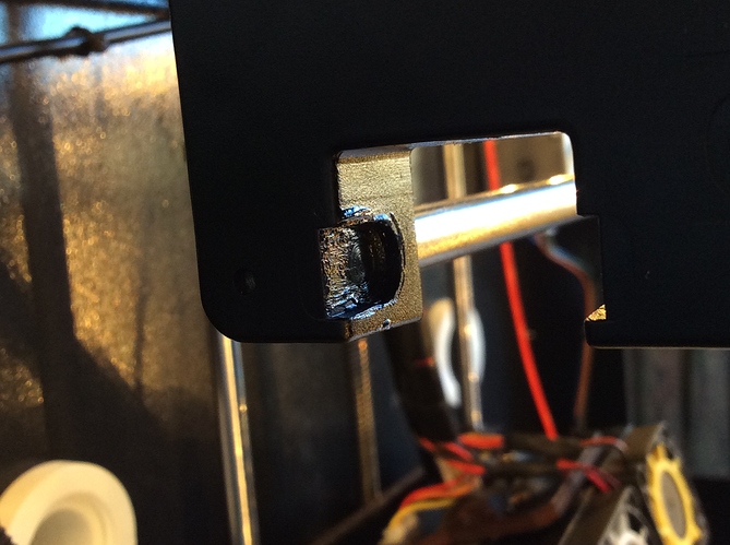
Removing the left Y-Axis and removing the X Carriage might seem quite daunting but in reality it’s just 4 screws and some muscle as the X-Axis rods can be quite firmly in place especially after 1000 hours of use, To remove the y axis you must undo the front screws below the top left corner on the front of the machine and the back of the machine be careful not to drop them down the corners like i did … several times. It would be a smart idea to put some blue tape over the inner corners.
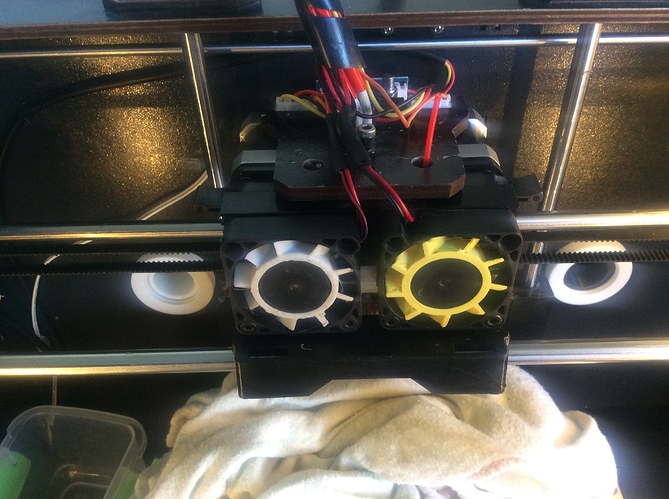
Once the screws are loose leave them in place and remove the extruder of the carriage and place onto something soft don’t directly rest it on the nozzles.
Step 3
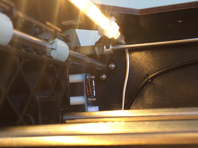
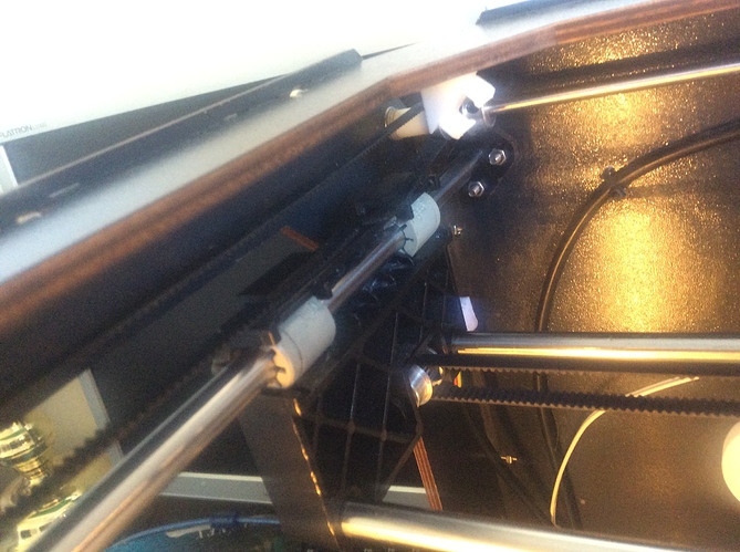
This is where it can get quite a handful and help from a friend would be quite handy, once the extruders are of you must loosen the X-Axis belt this can be done by either undoing the 4 stepper screws on the end of the carriage or by removing the belt clamp which are the other two screws underneath the carriage
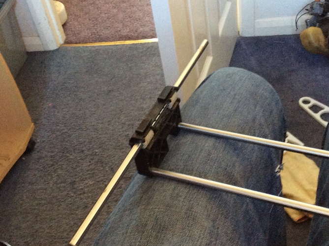
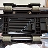
Once loosened completely remove the screws in the left hand side of the machine and put them in a box of some form so you don’t loose them ! Now comes a tricky part, removing the x axis rods can be quite tough but word of caution don’t just pull or push one axis as you can damage the machine this way, hold firmly the stepper side of the axis and pull the left side away from the right this way you are supporting both sides
Step 4
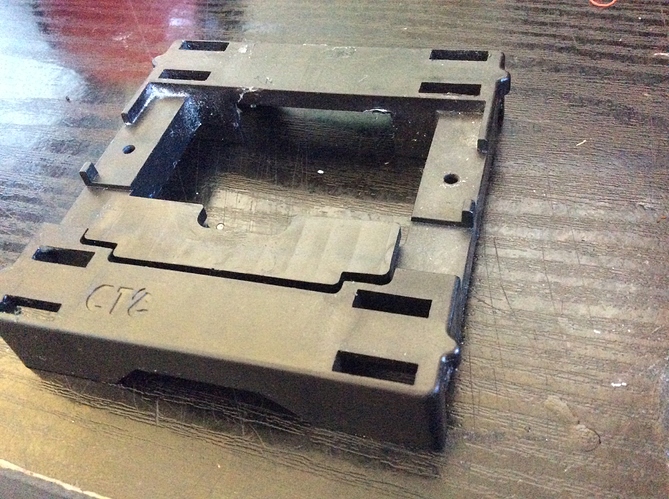
Either before you take the axis out you can remove the plastic X carriage of the rails by pushing down on the rails lightly and up on the front portion they will snap out and repeat for the other side. While disassembled it’s a great idea to clean your axis’s up as i first replaced my Y-Axis bearings as they were making horribly annoying noises and so there was still lots of grease on the arms of the carriage.
Don’t forget to take out your bearing on the left hand X-axis end !
Step 5
Good news you’re more than halfway done ! I would suggest taking a 5 min break for a drink as this can be quite tedious work! Once the carriage has been taken out can be quite finicky.
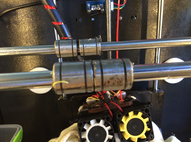
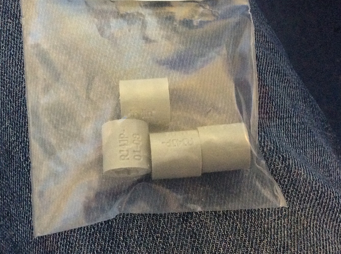
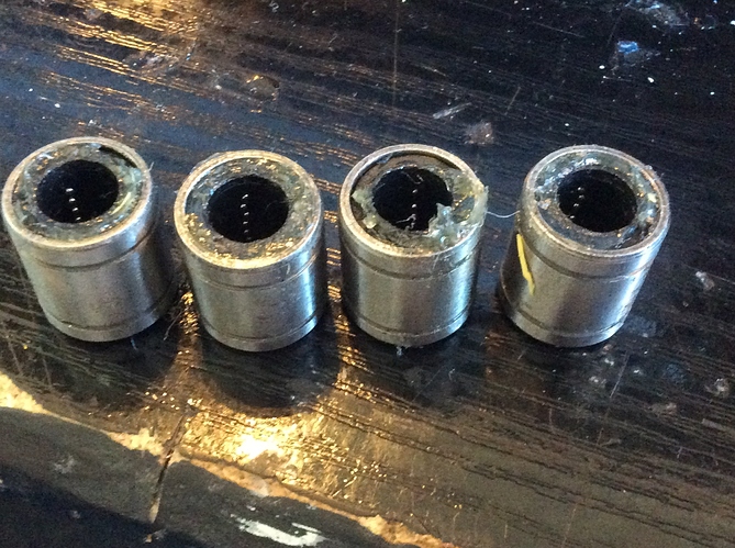
It’s time to take those horrible “Linear” bearings of and say hello to the new smooth IGUS Polymer bearings.
At this point you have two choices you can either buy standard size LM8UU bearings and cut them from 25MM down to 17MM or buy them from the same supplier as i got my second set from i can vouch for these and they are already pre-cut to size
http://www.ebay.co.uk/itm/Makerbot-Replicator-2-2X-IGUS-Lager-wartungsfrei-leise-maintenance-free-bushings-/252011586572?hash=item3aad0fa40c
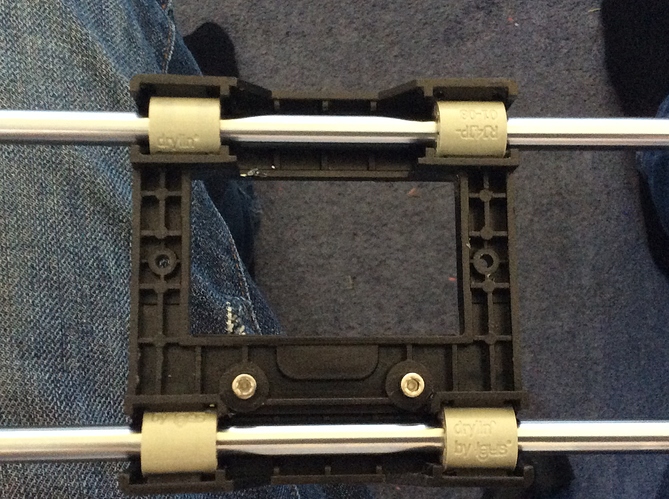
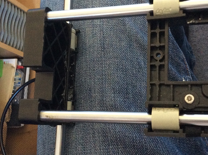
You can either install them on the axis and snap the carriage on to them but it is easier to just install them in the carriage and then slide it on to the axis rods.
Step 6
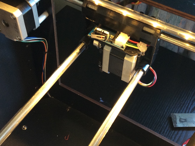
This step is just the reversal of the removal make sure the carriage isn’t installed backwards then just install the axis and rods into the stepper assembly side.
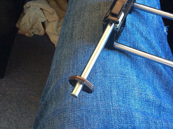
Make sure you put the ends on the rods to attach it to the frame!
Install the screws and nuts and tighten lightly then push each rod up and tighten fully by doing this you know that both of the rods are perfectly straight and true to each other.
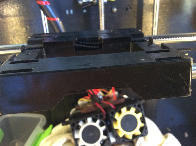
Re-install the X-Axis belt, if you took the stepper out to release the belt put the belt around the gear before reinstalling the stepper into the frame otherwise you will never get it back in. Once it is back in place push the stepper away from the x-carriage to put tension on the belt and tighten the allen screws.
When reattaching the belts for the Y-Axis push the axis from the centre to the back until the limit switch clicks then wrap the belts around the top of the gears and slide it into the first or rear slot on the x arm.
Do the same for the other side so when you pull the other side of the belt taut both sides will have equal load and tension and the axis will run straight and true to each other and make sure the top of the belt is taut to do this when installing the second part of the belt use the pliers to pull the belt as you will have better grip and pulling power and will be able to get the belt as tight as needed just don’t over tighten it!
Step 7 Final Step
Re-installing the extruders is as simple as taking them of 2 allen screws into the block and tighten gently… this is when i managed to strip the right hand thread of the block so be carefull if you manage to do what i did get a 3mm bottoming tap and re-tap the hole and use a slightly longer m3 screw so it has more of the block to bite into and you have less chance of stripping the screws !
And Relax…
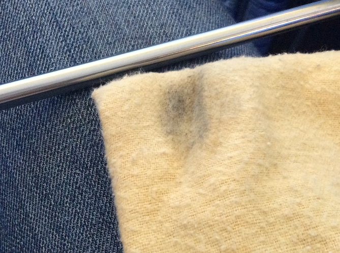
Forgot to mention when you have the rods of if you have used any sort of grease / lubricant use some acetone to wipe down the rods of any contaminants this will ease in binding and sticking.
When the bearings are new they can be quite stiff don’t worry just apply a very light amount of multi purpose grease of ptfe grease on the rods and slide the axis back and forwards with the machine switched on or you could damage your board from backwards voltage !
You have now gone from these horrible manky not so linear bearings
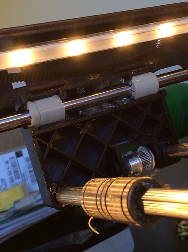
To these lovely, quiet very linear polymer bearings
This upgrade will help with ringing on parts, noise levels and generally make you love your printer that little bit more while the machine is apart you can also replace the Y-Axis bearings for even more stealth.
Hope you enjoyed and good luck with upgrading your own machine hope you succeed with the install and once you have had your machine apart once you start to worry less as you know what fails just by hearing or seeing and you now know how to get to it and fix it!
Print quality after upgrade!
0.35mm Layer height looks better than ever and so precise !
If any CTC owners want to know how to get there bed working properly so when you set it to a temperature it’s not actually 30 degrees below what it says let me know and i’ll take some photos and make another thread !