Hi all Just wanting to pick your collective brains. I’m building my own custom 3D printer it is a CoreXY design the CoreXY part I have all sorted and tested and I’m happy with that. I’m now doing the Z Axis, I was planning on supporting the Bed on all 4 corners (smooth-rod) Plus 2 Ballscrews on the sides at a central Point. however after finalising the design of the CoreXY stage I can no longer put the ballscrews at the sides as originally planned! so I’m now having to do a rethink I can either put one at the front and one at the back of the printer in the middle which will obstruct removing 3d printed parts from the front (but I can still access them from the side) or I could replace two opposite corners with ballscrews so that would be ballscrew then smooth-rod at the back and smooth-rod and ballscrew at the front or the last option is to just use one ballscrew at the back. what would you do ?

1 Like

Hey there,

So it looks like you are about to build a very sturdy printer. Unusual to have the bed supported at all 4 corners, but i dont think it would be bad at all… i thin manufacturers just dont do it and spend the extra money on other things… i dont realy know how you want to build it. Maybe make a quick 3d mockup or picture wich shows ur ideas so we can discuss about it. But i have a really good resource. Tec2C on Youtube recently build a CoreXY printer himself and made some very good improvements over lets say a typical UM clone. I´ll drop a link. Just watch the videos take from them what u need and report back with a little bit more information for us.

thats the first video of the series… have fun with it.

Best Regards,

Eddie.

OpenRobotX.

1 Like

Hey … I’ve been watching those videos… My design is using 20mm v slot extrusions it’s basically a 500mm3 cube with an over and under belt config hence the inability to now use the sides as the belts run there. I should have a pic. (Found one) it’s just a quick build I’ll replace the plastic corner pieces with metal ones (waiting for those) when the printer mechanicals are finished I’ll be using 3/4mm acrylic on the sides and top/bottom this will give the printer a more professional finish whilst also providing strength/rigidity to the whole printer. Colin's CoreXY (V-Slot) by zx81 - Thingiverse there’s more pics there and there should be one of the smooth-rod supports (I was originally going to use them for the coreXY stage but changed my mind)

Yeah so i think i would go with a ballscrew in the middle back. This is very common and known to work. and I also would only use one ballscrews… you can never get 2 stepper motors perfectly rotating the same speed except you get yourself some pretty beefy steppers. But with the Smoothrod assembly, i think you should just bring this thing to a working state with two smooth rods for the bed and watch if its bothering you that there are no 4. Get it running and mod it later. I think thats the best way to go about this.

Hope i could help. If you have morge questions just let me know.

Best Regards,

Eddie.

OpenRobotX.

2 Likes

Please only put a ball screw in the middle back if you can make a strong base for it. Forget linear rods, they are too week for such a force. The smallest diameter you can use is 20mm and it will flex also.

Use proper linear rail 12mm wide: https://www.aliexpress.com/item/MR12-12mm-linear-rail-guide-MGN12-length-500mm-with-mini-MGN12C-linear-block-carriage-miniature-linear/32334017152.html?ws_ab_test=searchweb0_0,searchweb201602_2_10065_10068_10084_10083_10080_10082_10081_10060_10061_10062_10056_10055_10054_301_10059_10099_10078_10079_426_10073_10102_10096_10052_10050_425_10051,searchweb201603_8&btsid=d04fbb40-2fce-491a-9d66-1aa826bc0e30

even the cheapest Chinese one will be much better then rods, but you will need 2 carriages on one rail to make a proper support structure from ALU like this have.

https://www.youtube.com/watch?v=6EtJfaiQ9H0

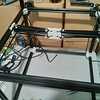
(also I would use these rails for x-y motion, instead of these wheel type stuff, also the frame is too week from 20mm profiles, i would use 30x30 at least, with proper metal corner pieces)

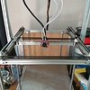
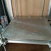
But If you add two more profiles per sides then you can mount the 2 ballcrews. 1204 would be sufficient with proper bk10 bf10 housings. Order 40 teeth GT2 pulley for it and a 20teeth for the motor, and a closed loop gt2 belt around 1200mm long, this will move table without any problems. And put 4 linear rods (16mm) to support the table move, not the edge but around 100mm sides-side from the ball screw. The table can made also from 20x20 profile with an aluplate mounted on the bottom (where all the bearings and ball screws are fixed).

And how I know this? I built a 400x400x650 printer for a client…and just in a progress with a 500x500x500 build volume printer for an other company. The problem is resonance as you crank up the speed on the printer (for such a big printer you must to finish the print in an acceptable time) ,100 mm/s is the normal print speed. If its frame or any other component has any backlash it will affect the print quality.

CNC machine parts are so cheap now days(like linear rails, ball screws etc.) that its not really worth to tinker with home made parts. (I would also skip the COREXY mechanics above 300x300mm x-y motion, and use normal cartesian mechanics with a 1:2 gear ratio on the Y axis, the belts will be too long and will flex, also please at least use the white GT2 belts with steel reinforced core, these fiber core ones are more like a rubber band).

Hope you understand my points, and no offense here, I just don’t want you to make mistakes. I have also learned this on the hard way…

Regards,

Tamas

All input is appreciated I’m going to stick with the 20mm v slot extrusions plenty of people are using them with no major issues, maybe for printer number 4 or a CNC I’ll look at guide rails. I’m not clear as to what you mean by “such a force” regarding the 10mm smooth rods… the rods will be verticle there essentially just guides there will be no direct force on them at all the ballscrew will be taking the load (which isn’t much) I’m already using 10mm gt2 belts I did look for reinforced ones however they were not available in GT2 I think you mean T2.5 belts ? Which are reinforced but they have an odd stepping and I don’t want to have to use a gear train on the coreXY part… Great reduction is already planned for the ballscrew (2:1) There will also be a sizable weight in the bottom of the printer as the power supply and electronics are going in there (and it’s a bit of a monster)

If you just put a ballscrew into the back and support it with two 10mm rods there will be plenty of play if you will grab the front of the table and move it up and down, so this will translate resonance of the table during print. You can say hey the table is just sits there during the print and moves just a tiny amount down some time, but during print and when making small infills or surface close 45degree movement the resonance will make the bed move compared to the nozzle.

To eliminate this I would use two ballscrews on the side and 2-2- smooth rods (the bigger the better) 16mm should sufficient, but for this you have to put in 2-2 extra extrusions per side to hold the ballscrew and the rods, Or just put one on the top and put big feets under the printer so the ballscrews end with pulley have enough space to rotate.

If you order the ballscrew from china you can ask them to do the end machining for you, but for this you need to design the table in CAD to have the exact length.

Regarding the frame please put back and side panels on it with a screw in every 100mm, this will make it much stronger.

10mm belts are the same as the 6 mm ones they just cut it wider during manufacture.

Steel reinforced belts are 6mm wide, and can’t find wider at china they don’t have it by default, Gates have it but the prize is not friendly.

I understand what you mean however that’s not what I’m planning to do, there will be 4 rod’s and one ballscrew, the 4 rods one at each corner and the ballscrew in the back centre. originally I was going to do 2 ballscrews at the sides and use a closed loop GT2 belt to link both of them to one stepper motor, but that’s no longer possible because of the over and under belt system.

I’ve already mentioned I’ll be using 3/4mm acrylic on the sides and top and bottom

the 4 rods will have 4 SCU10UU bearing blocks. I’ve added a picture of a crude mockup

I’ve got a similar set up to your build, see pics. 10mm rods with 2 lead screws. I started with the short bearings you’re planning on but found with a 400x400 bed there was far too much play. I could tilt the bed side to side quite easily, and that was using screws on both sides. Longer (10LUU) bearings fixed this. With one screw at the back I think you’ll get binding of the front bearings and jerky z moves. Also with a single ballscrew the weight of your build plate may turn the z motor when it isn’t powered.

1 Like

that’s helpful information

I like the look of your printer!

The other option I was considering was using 2 Rods and 2 Ballscrews at opposite corners I guess it’s something I’ll have to play around with … the 10LUU bearings I have dont seem to have much play in them at all but I’ll see how it goes once I get it assembled … just waiting for parts.

Thanks, it’s all good fun building these things. Going bigger is definitely a learning curve. Designs for smaller printers don’t necessarily scale up very well. Have you sourced a print bed yet?

the print bed I’m not worried about … I can use my 200x200mm bed in the mean time I mainly only print fairly small things however I do want to do a couple of large pieces just to sit on my desk.

I have already designed an Aluminium bed I just need to send it away to get it cut … and 400x400mm silicone heaters are quite easy to get.

I like those guide rails you have on yours I think I might do the same … when budget allows … not really the best time of year for expendable cash when Christmas is just round the corner.

how is your printer for bed alignment … I’m currently using a P3Steel and because it’s all laser cut I just measured the distance with a calliper on all 4 corners of my bed and I pretty much never need to calibrate it. I’m hoping it’s going to be the same with this CoreXY (although I have already purchased an inductive sensor just in case)